How does the LoRa module implement the air wake up function
Jun . 2021
In the design of wireless sensor networks, most terminal nodes require air wake-up to complete the design requirements of low-power design. So how does the LoRa module achieve wake-up in the air? This article will reveal to you.
In wireless sensor network design, most of the LoRa module transceiver node srequire low power processing. In order to reduce power consumption, the node needs to reduce useless working hours. In most IoT applications, the radio partis in the receiving state most of the time during wireless communication, andit is also the main energy consumption. The node can not be in active state at all time because the battery capacity is limited . The ideal state is that when there is data to be received, the node is in the receiving state, and when no information is received, the LoRa node is in a sleep state, which requires anair wake-up technique.
The phenomenon that wake_up over the air seems to be that the transmitter wakes up the receiver from sleep. In fact, the receiver wakes up periodically and checks whether there is a valid signal in the air. If not, it continues to sleep; if there is, then Waken into the receiving state. Therefore, when there is no valid signal in the air, the average power consumption of the receiver is low.
However,how to find the call signal is traditionally determined by setting the RSSI value. Only when the signal strength is sufficient, it is considered valid, and the node is awakened, otherwise it is the opposite. The use of a spreadspectrum modulation technique presents challenges in determining whether the channel is already inuse by a signal that may be below the noise floor of the receiver. The use of the RSSI in this situation would clearly be impracticable.To this end the channel activity detector is used to detect the presence ofother LoRa® signals.To solve this problem, CAD channel activity detection technology can be used to detect other LoRa signals.
The LoRa packet consists of a preamble, an optional header, and a data payload, as shown in the following figure:

The channel activity detection mode is designed to detect the LoRa preamble on the wireless channel with the highest possible power consumption efficiency. In CAD mode, the LoRa module will quickly scan the band to detect the LoRa packetpreamble.
The following operations are performed during the CAD process:
The PLL is locked.
The radio receiver captures LoRa preamble symbol of data from the channel. The radio current consumption during that phase corresponds to the specified Rx mode current.
The wireless receiver and PLL are turned off and modem digital processing begins.
The modem searches for a correlation between the radio captured samples and the ideal preamble waveform. This correlation process takes a little bit less than a symbol period to perform. The radio current consumption during that phase is greatly reduced.
After the calculation is completed, the modem generates a CadDone interrupt signal.If the association is successful, a CadDetected signal is generated at the sametime.
The chip goes back to standby mode.
If the preamble is found, the interrupt is cleared, and then the chip is set to Rxsingle or continuous mode to begin receiving data.
The time taken for the channel activity detection is dependent up on the LoRa modulation settings used. For a given configuration the typical CAD detection time is shown in the graph below, expressed as a multiple of the LoRa symbolperiod. Of this period the radio is in receiver mode for (2 SF + 32) / BW seconds. For there mainder of the CAD cycle the radio is in a reduced consumption state.
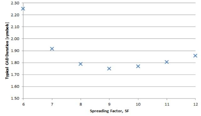
The CAD program is broken down into multiple events in sequence to better illustrate the program and power consumption, as shown in the following figure:
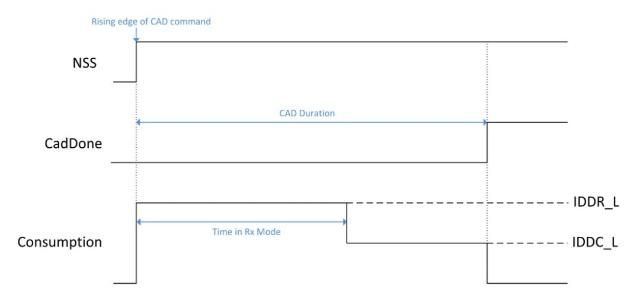
IDDR_L:full Rx mode
IDDC_L:Low power processing
During the channel activity detection process, the receiving end is in the full receiving mode only for the first half of the time, and then enters the low power processing phase, during which the CAD power consumption changes with the LoRa bandwidth.
Since the CAD detects the preamble part of the data packet, in order to achieve the air wake-up, combined with the node periodically detecting the time, it is necessary to set the appropriate preamble transmission time to ensure the preamble transmission time > the node periodic detection time, then acertain preamble needs to be set. The code length can be achieved by configuring the RegPreambleMsb and RegPreambleLsb registers. As shown in the figure below, you can change the length of the transmit preamble by setting the preamble register length between 6-65536.

 +86-755-23080616
 sales@nicerf.com
Website: https://www.nicerf.com/
Address: 309-314, 3/F, Bldg A, Hongdu business building, Zone 43, Baoan Dist, Shenzhen, China


 English


