How to properly set the wireless module
When developing with wireless functions, developers almost always choose wireless modules or wireless chips. Sometimes, developers often spend a long time setting the parameters because they do not understand the various parameters of the wireless module. In fact, after following certain principles, the parameters of the wireless module become very simple. This article describes how to choose the appropriate parameters.
First of all, we must clarify which parameters we can set artificially. Generally speaking, there are mainly the following parameters:
1. Frequency. Countries around the world have different permission ranges for open and unlicensed frequencies. When setting this parameter, it needs to be set within the allowable range according to relevant local laws and regulations. When developers set specific frequency values, they often set the value corresponding to the write rate to the corresponding register according to the chip's specification.
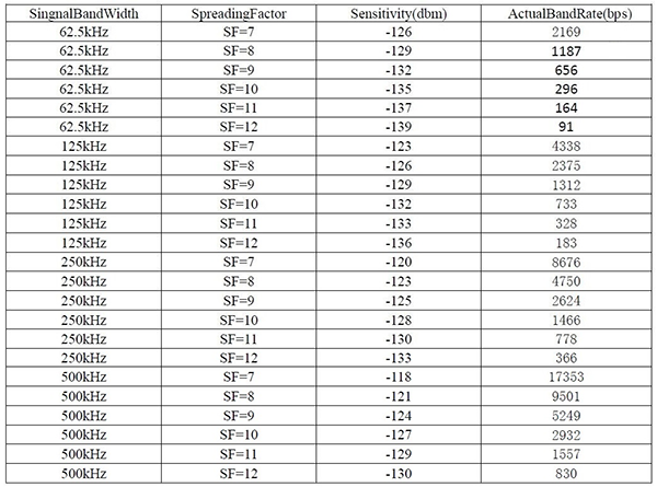
2. Speed. The rate determines the data transmission speed, and this parameter is easy to understand. However, for many chips, the speed is not an existing parameter. A certain value of the rate often depends on other parameters, such as modulation method, bandwidth, spreading factor (LoRa type chip or module). For example, take SX1262 as an example. This is a new chip that supports LoRa modulation technology. Based on this chip, Siwei Wireless has also developed a front-end module and a digital transmission module. In the SX1262 chip reference manual, there is no clear chapter on how to set the rate. But as mentioned earlier, the speed of a wireless chip is often determined by multiple parameters, so is there a clear correspondence? The answer is yes. Take the ultra-low receiving power and high-power wireless transceiver module LoRa1262F30 developed by Think Wireless as an example. The settings of its rate and other parameters are shown in the following table:

From the above table, we can clearly see the corresponding relationship between the speed and other parameters, which brings a lot of convenience to our development process. What needs to be pointed out here is that the higher the rate, the better. Under other conditions unchanged, the speed is inversely proportional to the anti-interference performance of the chip and the transmission distance. Specifically: the higher the rate, the shorter the transmission distance of the wireless module, and the transmission process is more prone to errors (anti-interference ability becomes lower). During the development process, developers should set these parameters reasonably according to actual requirements.
3. Bandwidth. Bandwidth refers to the frequency width occupied by the signal. As mentioned earlier, this parameter table is a parameter that affects the rate. This parameter should be selected according to the actual situation.
4. Modulation method. Commonly used modulation methods for wireless modules include LoRa, FSK, OOK, etc. According to actual experience, the maximum data transmission rate of a wireless module using fsk modulation is much faster than that of a wireless module using LoRa modulation technology. For example, SX1262 supports two debugging methods, LoRa and FSK. The speed is faster when FSK modulation is used, and only one method is generally selected for actual development.
5. Frequency offset, this can be set according to the manufacturer's reference manual.
6. The length of the preamble. The wireless module judges when there is a new data packet based on the content of the locked preamble. If the length of the preamble is too short, the receiver will frequently detect the wrong signal and wake up, and the power consumption will increase; and if the length of the preamble is too long, the receiver needs to pass through when the wireless signal is locked. It takes longer to receive data packets. Therefore, the length of the data packet should be set to an appropriate value so that the chip can receive data quickly and accurately. Generally, the chip manufacturer will give a recommended value for the user of the preamble.
7. Spreading factor (only for chips with LoRa modulation mode) During spreading, each bit of data is multiplied by the spreading factor. For example, there is a 1 bit to be transmitted. When the spreading factor is 1, data is being transmitted. 1 is represented by a 1, and when the spreading factor is 6 (with 6 bits) 111111, 111111 will represent 1, so that each bit is represented by a 6-bit data, which means that the total transmission The amount of data increased by 6 times.
In this way, the transmission after spreading can reduce the bit error rate, which is the signal-to-noise ratio, but under the same data volume condition, it reduces the actual data that can be transmitted. Therefore, the larger the spreading factor, the greater the number of data transmitted (bit rate). The smaller.
The above is a summary of the wireless module parameter settings. After the above introduction, I believe everyone has a clear understanding of wireless communication parameter settings. Hope this article can help you all.
 +86-755-23080616
 sales@nicerf.com
Website: https://www.nicerf.com/
Address: 309-314, 3/F, Bldg A, Hongdu business building, Zone 43, Baoan Dist, Shenzhen, China


