


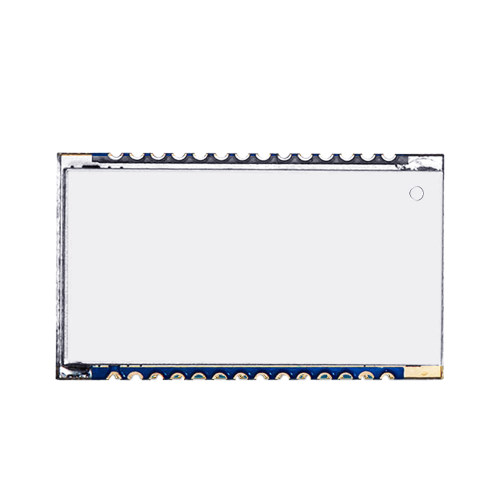
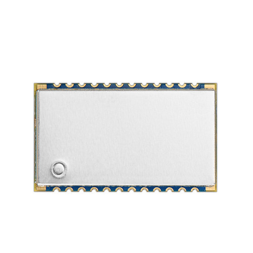
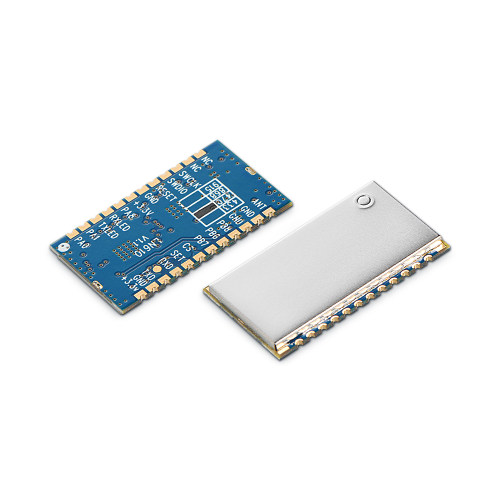
LN610-X1 : 100mW LoRaWAN Node RF Module
Modulation: LoRa
Chip: Others
Output Power: 100mW
Frequency: Others
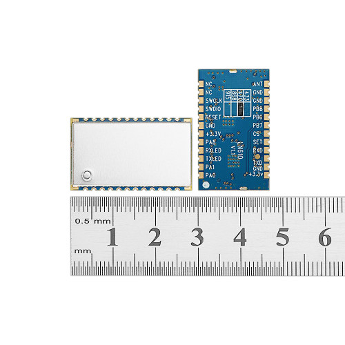
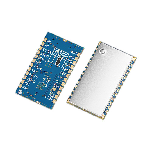
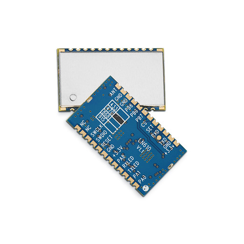
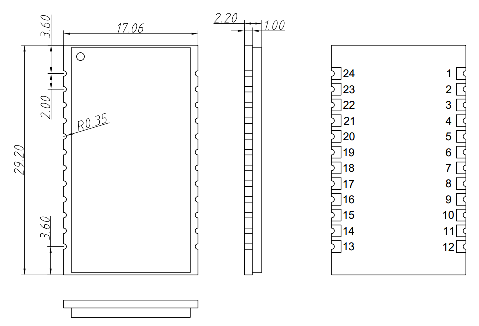
Size:36.99*21.29
★ Note: the following parameters is VCC = 3.3, with 50 ohm copper axis test instrumentation.
| Parameter | Min | Typ | Max | Unit | Condition |
| Working Condition | |||||
| Working voltage range | 1.8 | 3.3 | 3.6 | V | |
| Temperature voltage | -40 | 85 | ℃ | ||
| Current Consumption | |||||
| Receiving current | 18 | mA | @Vcc=3.3v | ||
| Transmitting current | 100 | 110 | 120 | mA | Vcc=3.3v,Tx=20dBm |
| Sleep current | <2 | 3 | uA | CS Active H | |
| RF Parameter | |||||
| TX Power | 4 | 18 | 20 | dBm | |
| Receiving sensitivity | -131 | -132 | -133 | dBm | @BW=125KHz,SF=10 |
| 2nd Harmonic radations | -45 | dBm | |||
| 3rd Harmonic radiations | -50 | dBm | |||
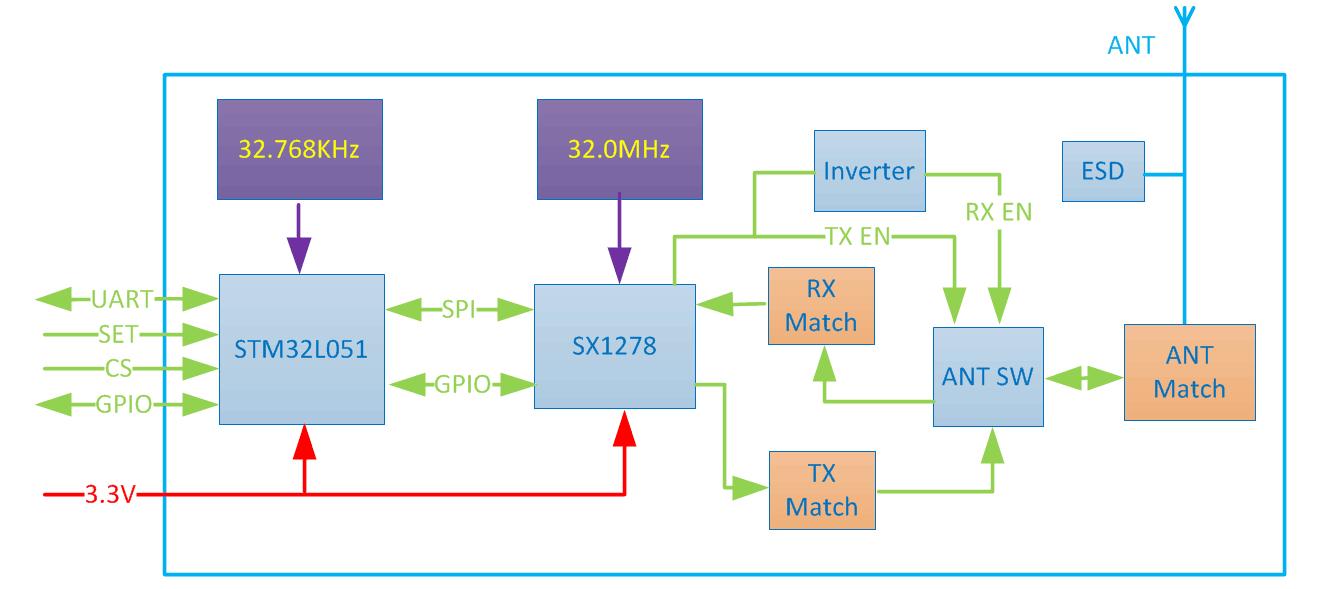
| Interface | Uart |
| Output Power | 100mW |
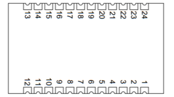
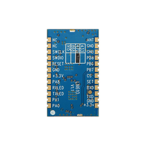
| Pin | Pin Name | Type | Description |
| 1 | PA0 | I/O | Reserved |
| 2 | PA1 | I/O | Reserved |
| 3 | PA2/TXLED | Output | LED blinks when tx,Active low |
| 4 | PA3/RXLED | Output | LED blinks when data received,Active low |
| 5 | PA8 | I/O | Reserved |
| 6 | +3.3V | Power (VCC) | Power Supply(Typical voltage) |
| 7 | GND | Power (GND) | Ground |
| 8 | RESET | Input | Reset the module |
| 9 | PA13/SWDIO | I/O | Reserved for factory firmware upgrade |
| 10 | PA14/SWCLK | I/O | Reserved for factory firmware upgrade |
| 11 | NC | ||
| 12 | NC | ||
| 13 | ANT | Antenna | Connect with 50 ohm coaxial antenna |
| 14 | GND | Power (GND) | Ground |
| 15 | GND | Power (GND) | Ground |
| 16 | PB8 | I/O | Reserved |
| 17 | PB6 | I/O | Reserved |
| 18 | PB7 | I/O | Reserved |
| 19 | PB1/CS | Input | 0: working mode,1: sleeping |
| 20 | PB2/SET | Input | 0: setting mode, 1: normal working |
| 21 | PA10/RXD | Input | RXD of this module, |
| 22 | PA9/TXD | Output | TXD of this module |
| 23 | GND | Power (GND) | Ground |
| 24 | +3.3V | Power (VCC) | Power Supply(Typical voltage) |
Privacy Policy
· Privacy Policy
There is currently no content available
Email:sales@nicerf.com
Tel:+86-755-23080616