

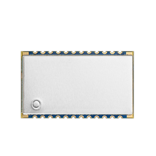
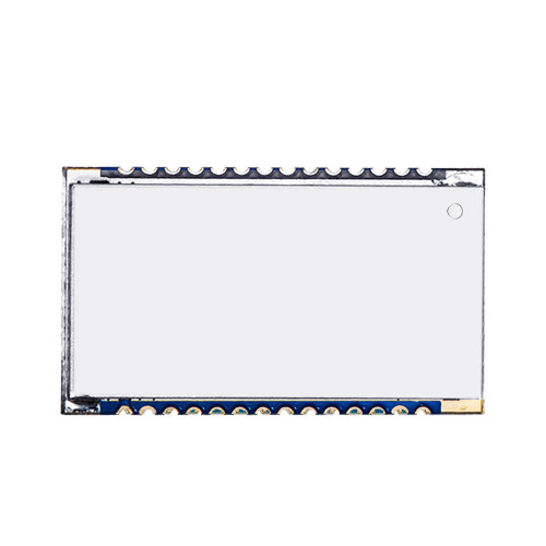
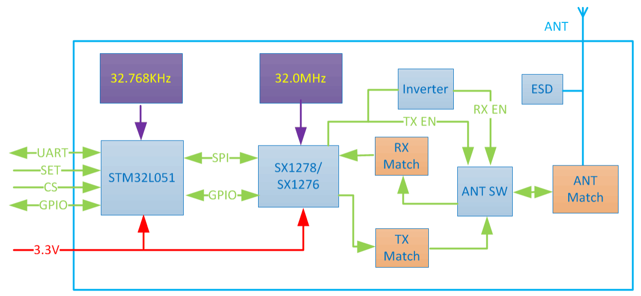
LN610 : 100mW Small Size LoRaWAN Node RF Module
Modulation: LoRa
Chip: Others
Interface: UART
Output Power: 100mW
Frequency: Others
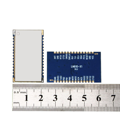
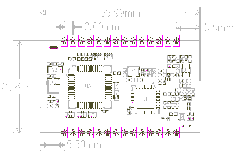
Size:29.20*17.06
Note: No LDO on board, the power supply should be : 1.8 –3.6V . 3.3V is suggested .
The following parameters is VCC=3.3V, with 50 ohm copper axis test instrumentation.
| Parameter | Min | Typ | Max | Unite | Condition |
| Working Condition | |||||
| Working voltage range | 1.8 | 3.3 | 3.6 | V | |
| Temperature voltage | -40 | 85 | ℃ | ||
| Current Consumption | |||||
| Receiving current | 18 | mA | @Vcc=3.3V | ||
| Transmitting current | 110 | 120 | 130 | mA | Vcc=3.3V,Tx=20dBm |
| Sleep current | < 2 | 3 | uA | CS Active H | |
| RF Parameter | |||||
| TX Power | 4 | 18 | 20 | dBm | |
| Receiving sensitivity | -131 | -132 | -133 | dBm | @BW=125KHz,SF=10 |
| 2nd Harmonic radations | -45 | dBm | |||
| 3rd Harmonic radiations | -50 | dBm | |||
| Output Power | 100mW |
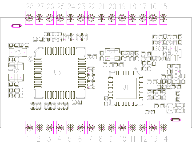
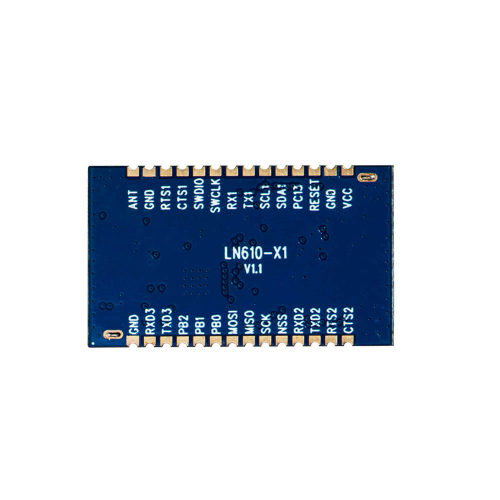
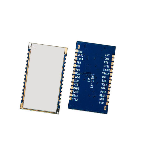
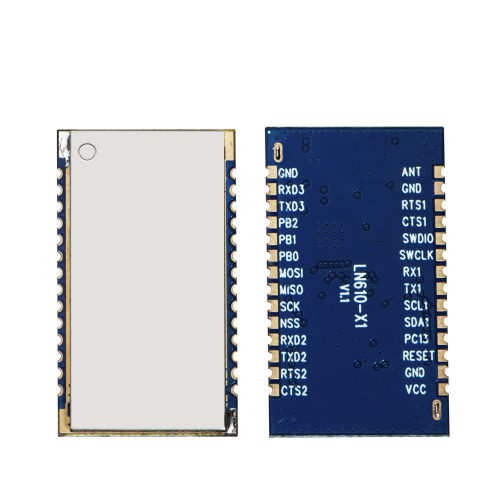
| Pin | Pin Name | Type | Description |
| 1 | CTS2 | I/O | UART2_CTS / GPIO |
| 2 | RTS2 | I/O | UART2_RTS / GPIO |
| 3 | TXD2 | I/O | UART2_TXD / GPIO |
| 4 | RXD2 | I/O | UART2_RXD / GPIO |
| 5 | NSS | I/O | SPI1_NSS / GPIO |
| 6 | SCK | I/O | SPI1_SCK / GPIO |
| 7 | MISO | I/O | SPI1_MISO / GPIO |
| 8 | MOSI | I/O | SPI1_MOSI / GPIO |
| 9 | PB0 | I/O | GPIO |
| 10 | PB1 | I/O | GPIO |
| 11 | PB2 | I/O | GPIO |
| 12 | TXD3 | I/O | UART3_TXD / GPIO |
| 13 | RXD3 | I/O | UART3_RXD / GPIO |
| 14、16、27 | GND | GND | Ground |
| 15 | ANT | Antenna | Connect with 50 ohm coaxial antenna |
| 17 | RTS1 | I/O | USART1_RTS / GPIO |
| 18 | CTS1 | I/O | USART1_CTS / GPIO |
| 19 | SWDIO | I/O | Firmware download / Debug |
| 20 | SWCLK | I/O | Firmware download / Debug |
| 21 | RX1 | I/O | USART1_RXD1 / GPIO |
| 22 | TX1 | I/O | USART1_TXD1 / GPIO |
| 23 | SCL1 | I/O | I2C1_SCL / GPIO |
| 24 | SDA1 | I/O | I2C1_SDA / GPIO |
| 25 | PC13 | I/O | GPIO |
| 26 | RESET | Input | Reset of MCU |
| 28 | VCC | Power (VCC) | Power Supply(Typical voltage) |
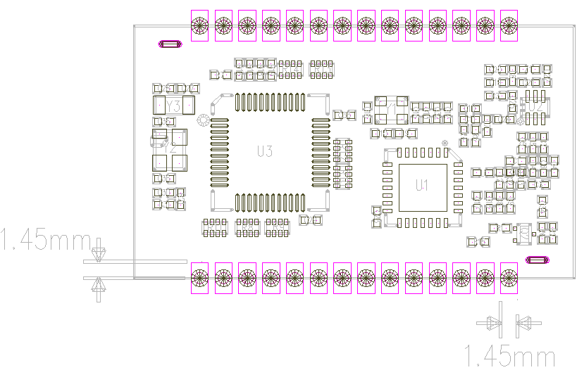
Maximum height: 2.7mm
Privacy Policy
· Privacy Policy
There is currently no content available
Email:sales@nicerf.com
Tel:+86-755-23080616