
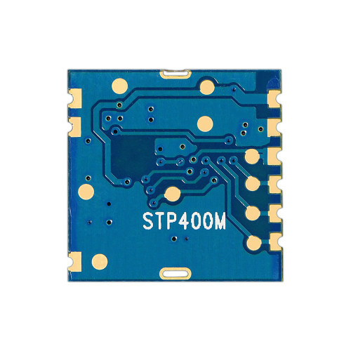
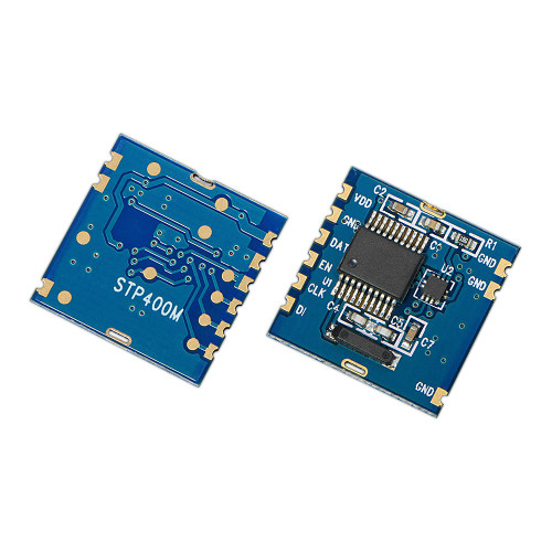
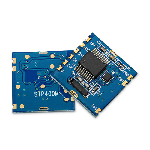
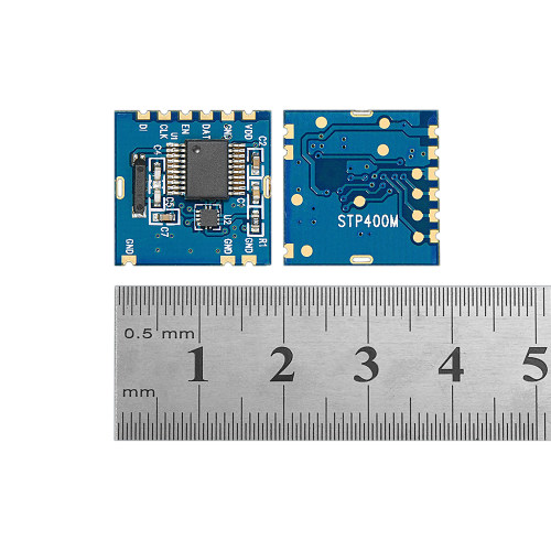
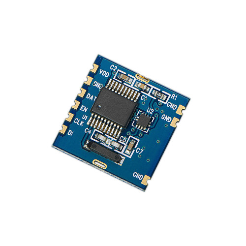
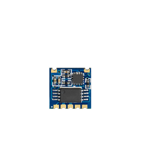
STP201M : IIC Interface Wrist Applicaton 3D Pedometer Module
Package : IC
Interface: IIC
Application: Wrist
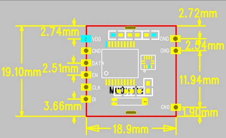
Size:9*8.72
| Parameter | Condition | Performance | Unit | ||
| Min | Typ | Max | |||
| Working voltage | 2.3 | 3 | 3.6 | V | |
| Working current | @3V | l | 20 | uA | |
| Pedometer resolution | 1 | Step | |||
| Working temperature | -40 | 85 | ℃ | ||
| Special Function | Pedometer module |
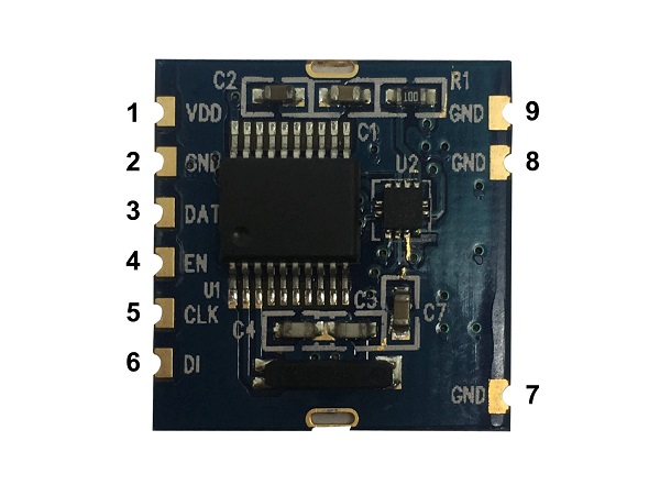
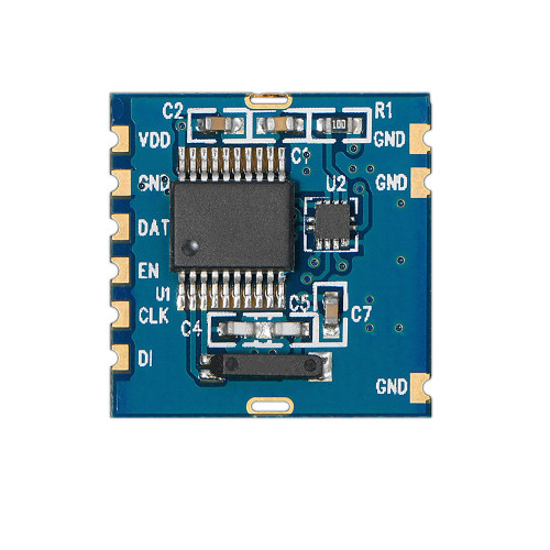
| Pin number | Pin name | Description |
| 1 | VDD | Connected power supply |
| 2,7,8,9 | GND | Power ground |
| 3. | DATA | Data output |
| 4 | EN | Communication enable input, high effective, usually low. After EN is high, it needs to delay 100ms to start communication |
| 5 | CLK | Communication clock signal input, CLK is high and DATA changes, CLK is low, the master reads DATA |
| 6 | D1 | NC |

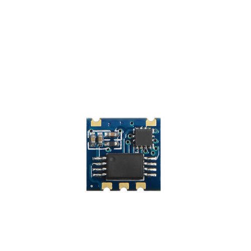
Package : IC
Interface: IIC
Application: Wrist
Size:9*8.72
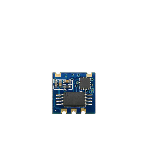
Package : IC
Interface: IIC
Application: Wrist
Size:9*8.72
Package : IC
Application: Non Wrist
Size:9*8.72
Package : IC
Application: Non Wrist
Size:9*8.72
Privacy Policy
· Privacy Policy
There is currently no content available
Email:sales@nicerf.com
Tel:+86-755-23080616