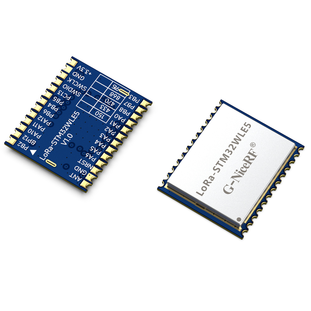
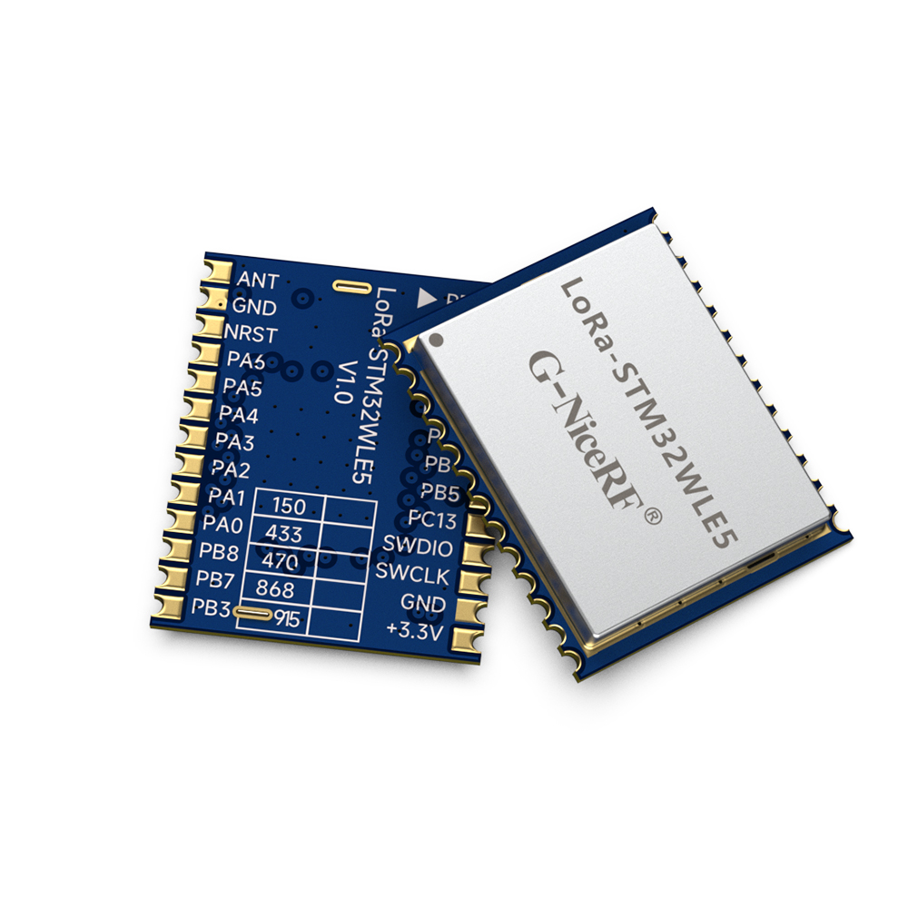
LoRa-STM32WLE5: SOC Wireless Module with Ultra-Small Size Built-in ARM Cortex-M4 Core
Parameters | Test condition | Min. | Typ. | Max | Unit |
Voltage range | 1.8 | 3.3 | 3.6 | V | |
Operating Temperature | -40 | 25 | 85 | ℃ | |
Maximum Input Signal | 10 | dBm | |||
Current Consumption | |||||
Transmit Current | @3.3v | <120 | mA | ||
Receive Current | <8 | mA | |||
Sleep Current | <1 | uA | |||
RF Parameters | |||||
Frequency Range | @433MHz | 400 | 460 | MHz | |
@470MHz | 470 | 510 | MHz | ||
@868MHz | 850 | 890 | MHz | ||
@915MHz | 900 | 940 | MHz | ||
Transmit Power | 20 | 21 | 22 | dBm | |
Receive Sensitivity | @BW=125KHz,SF=12 | -141 | dBm | ||
Frequency Error | 10 | ppm | |||
Modulation Rate | @LoRa | 0.018 | 62.5 | kpbs | |
@FSK | 0.6 | 300 | kpbs | ||
UHF band frequency:433/470MHz, 868/915MHz
Customizable frequency range from 150 to 960 MHz
Open area transmission distance of over 5000 meters
High receiver sensitivity up to -141dBm @ BW=125KHz, SF=12
Adjustable transmit power, up to 22dBm
Diverse interfaces: UART, SPI, I2C, GPIO, ADC
Sleep current:< 2uA
Receive current:< 10mA
Core processor: 32-bit Arm® Cortex®-M4 CPU
Security features: Supports 256-bit hardware encryption and PCROP read-write protection
Compact size with stamp hole design, facilitating secondary development by customers
Application
Smart Agriculture
Industrial Manufacturing
Smart Home
Remote Irrigation
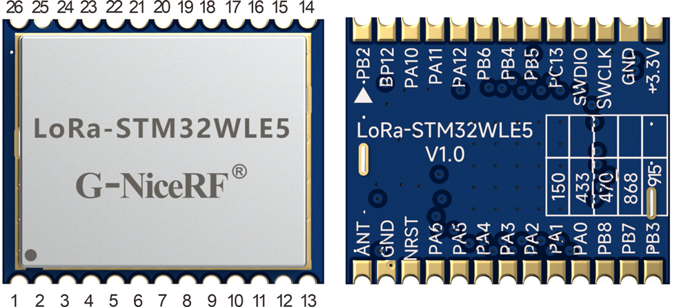
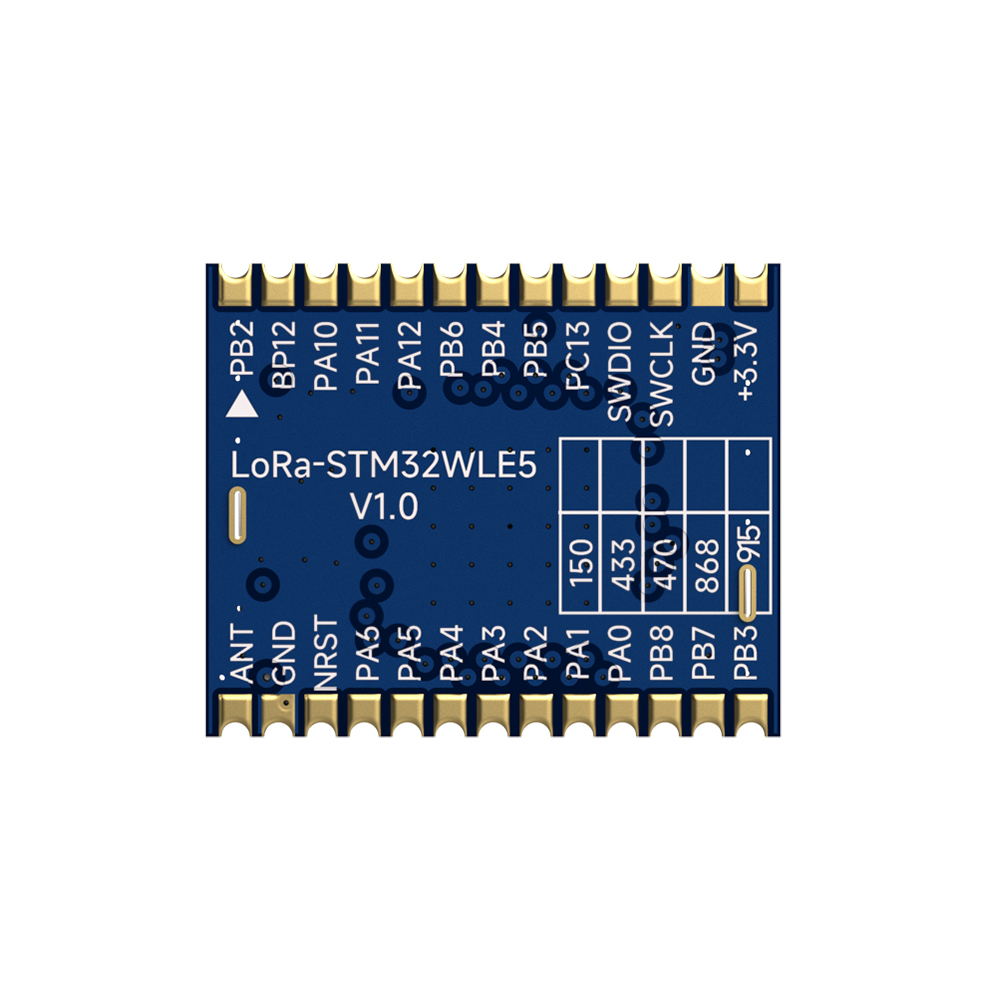
Pin NO. | Pin name | I/O | Description |
1 | PB2 | IO | Microcontroller I/O of the embedded chip; refer to the chip specification for functions. |
2 | PB12 | IO | Microcontroller I/O of the embedded chip; refer to the chip specification for functions. |
3 | PA10 | IO | Microcontroller I/O of the embedded chip; refer to the chip specification for functions. |
4 | PA11 | IO | Microcontroller I/O of the embedded chip; refer to the chip specification for functions. |
5 | PA12 | IO | Microcontroller I/O of the embedded chip; refer to the chip specification for functions. |
6 | PB6 | IO | Microcontroller I/O of the embedded chip, see chip specification book for specific functions. |
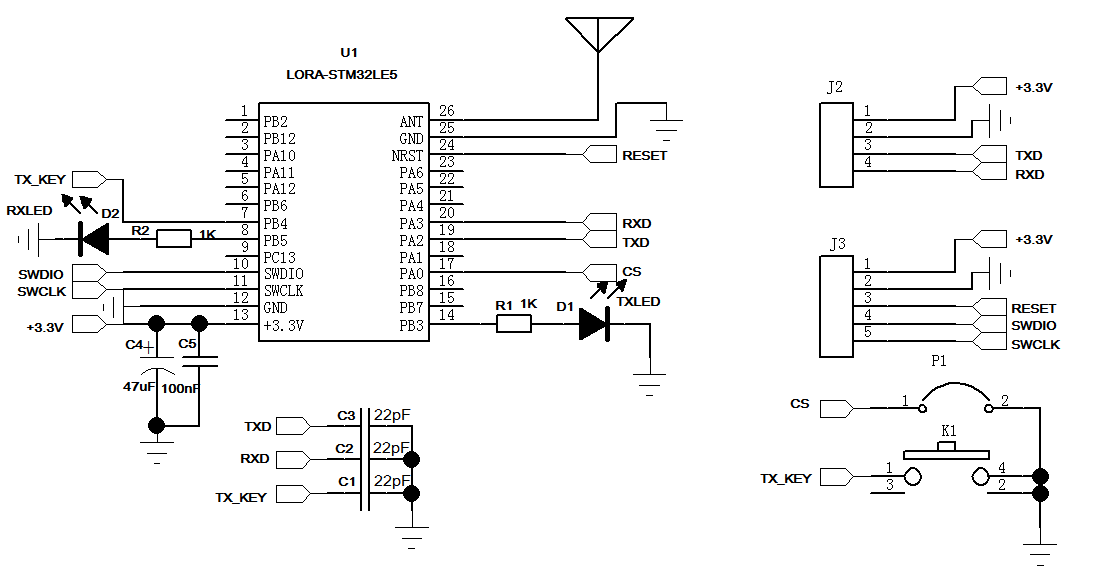
7 | PB4 | I | Microcontroller I/O of the embedded chip, DEMO program defines the transmit button pin; pressing the button transmits data. |
8 | PB5 | IO | Microcontroller I/O of the embedded chip, DEMO program defines the receive indicator pin; outputs high when data is received, otherwise low level. |
9 | PC13 | IO | Microcontroller I/O of the embedded chip, see chip specification book for specific functions. |
10 | SWDIO | IO | Microcontroller I/O of the embedded chip, programming interface. |
11 | SWCLK | I | Microcontroller I/O of the embedded chip, programming interface. |
12 | GND | - | Connect to the negative power supply. |
13 | VCC | - | Connect to the positive power supply. |
14 | PB3 | IO | Microcontroller I/O of the embedded chip, DEMO program defines the transmit indicator pin; outputs high when transmitting, low when not transmitting. |
15 | PB7 | IO | Microcontroller I/O of the embedded chip, see chip specification book for specific functions. |
16 | PB8 | IO | Microcontroller I/O of the embedded chip, see chip specification book for specific functions. |
17 | PA0 | IO | Microcontroller I/O of the embedded chip, DEMO program defines CS. |
18 | PA1 | IO | Microcontroller I/O of the embedded chip, see chip specification book for specific functions. |
19 | PA2 | IO | Microcontroller I/O of the embedded chip, DEMO program defines TXD. |
20 | PA3 | IO | Microcontroller I/O of the embedded chip, DEMO program defines RXD. |
21 | PA4 | IO | Microcontroller I/O of the embedded chip, see chip specification book for specific functions. |
22 | PA5 | IO | Microcontroller I/O of the embedded chip, see chip specification book for specific functions. |
23 | PA6 | IO | Microcontroller I/O of the embedded chip, see chip specification book for specific functions. |
24 | NRST | I | Microcontroller I/O of the embedded chip, chip reset pin, active low. |
25 | GND | - | Connect to the negative power supply. |
26 | ANT | Connect to an external 50-ohm antenna. |
