SX1280 LoRa module ranging demo board function tutorial
Jun . 2022
The LoRa module LoRa1280 series is our main product series. The core chip adopts Semtech's SX1280 radio frequency chip, which uses the LoRa modulation mode, works in the 2.4GHz frequency band, and has the ranging function. Has a good receiving sensitivity and anti-interference ability. Below is an introduction to our Demo board.
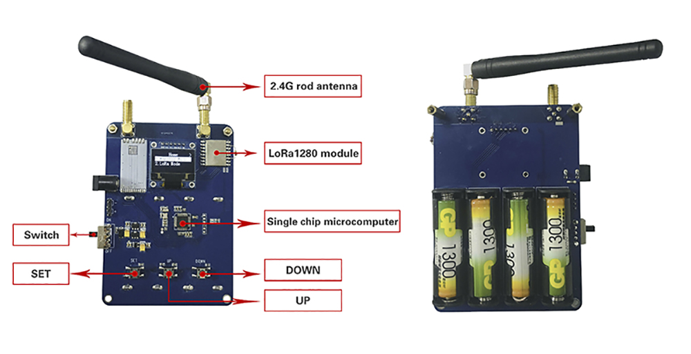
(SX1280 LoRa module Ranging Demo Board)
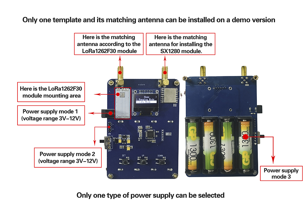
PS: The SX1280 Ranging Demo Board can be powered on the front side in addition to the No. 5 battery. Only one of the three methods can be selected. (If the power is supplied at the same time, the ranging demo board will be burned out)
1. Function description of SX1280 LoRa module demo board
The SX1280 LoRa module ranging demo board mainly implements the ranging demonstration function of the SX1280 and the two-way communication in the LoRa mode. And parameter modification in both modes.
2. Button function of SX1280 LoRa module demo board
There are three buttons on the demo board, which are SET button, UP button and DOWN button. The functions are as follows:
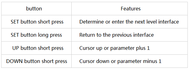
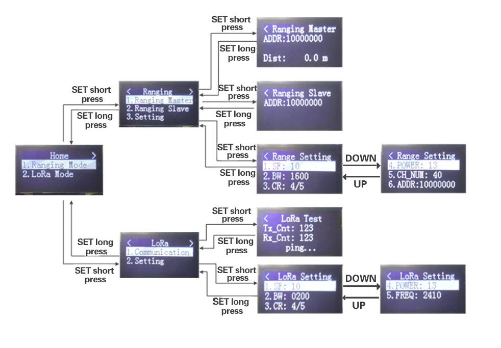
Operation method: normal power supply, toggle the power switch, turn on the power, the main interface will appear on the LCD screen of the ranging demonstration board. The main interface has two categories: Ranging Mode and LoRa Mode. Select to enter an option and press the SET button to return. Press and hold SET. Move the cursor up and down by pressing the up button and short pressing the DOWN button. The RangingMode interface is divided into three main options: Ranging Master, Ranging Slave and Setting. The LoRa Mode interface is divided into two major options: Communication and Setting. The function and operation of each option are described below.
3. Interface description of SX1280 LoRa module demo board
3.1 Main interface
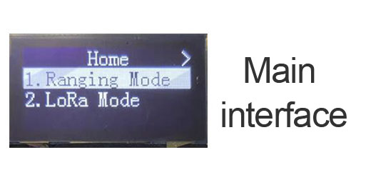
3.2 Select Ranging mode from the main interface, press SET button to enter the ranging mode interface, long press the SET button to return to the main interface from the ranging mode interface.
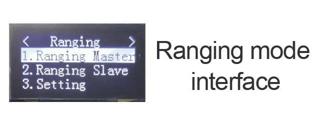
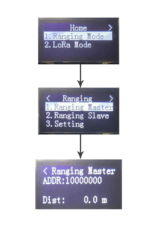
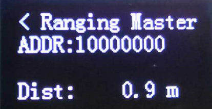
3.2.1 Select Ranging Master from the Ranging Mode interface and press the SET button to enter the Ranging Host interface. Press and hold the SET button to return to the Ranging Mode interface from the Ranging Host Interface. When the host is in the range, the host enters this interface and can display the distance.
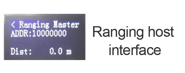
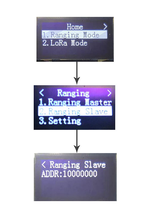
3.2.2 Select Ranging Slave from the ranging mode interface. Press SET button to enter the slave interface. Press and hold the SET button to return to the ranging mode interface from the distance measuring slave interface. The slave enters this interface during ranging;
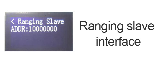
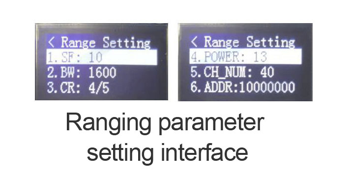
3.2.3 Selecting from the ranging mode interface Setting Short press SET button to enter the ranging parameter setting interface Set. There are two pages in the distance measurement parameter setting interface. Press the UP and Down keys to select the parameter to be set. Press the SET button to start the modification. Press the Up or DOWN button to modify the set parameters. Finally, press the SET button to complete the modification.
a. SF: propagation factors
b. BW: bandwidth
c. CR: Coding rate
d. POWER: power
e. CH_NUM: Channel number
f. ADDR: address
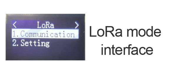
3.3 Select LoRa mode from the main interface Press the SET button to enter the LoRa mode interface. Press and hold the SET button to return to the main interface from the LoRa mode interface.
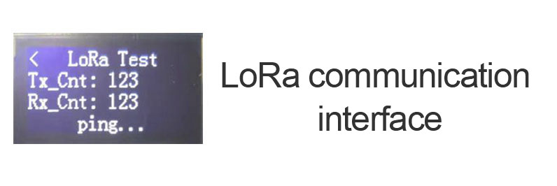
3.3.1 Select Communication from the LoRa mode interface and press the SET button to enter the LoRa communication interface. Press and hold the SET button to return to the LoRa mode interface from the LoRa communication interface. When LoRa transceiver communication display, enter this interface, without setting master and slave, the module will automatically switch;
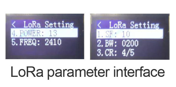
3.3.2 Select Setting from the LoRa mode interface and press the SET button to enter the LoRa parameter setting interface. Press and hold the SET button to return to the LoRa mode interface from the LoRa parameter setting interface. The LoRa parameter setting interface has two pages. To jump to the next page, press the DOWN button to short press. To jump back to the previous page, press the UP button to short press. The method of setting parameters is as follows: move the cursor to the option to modify the parameter, short press the SET button to select, short press the up button and the DOWN button to modify the set parameters, and finally press the SET button to complete the modification.
a. SF:Communication factor
b. BW:bandwidth
c. CR:Coding rate
d. POWER:Channel number
e. FREQ:frequency
3.4 Interface diagram
SX1280 LoRa module ranging demonstration board communication test and ranging operation method
Ranging operation:
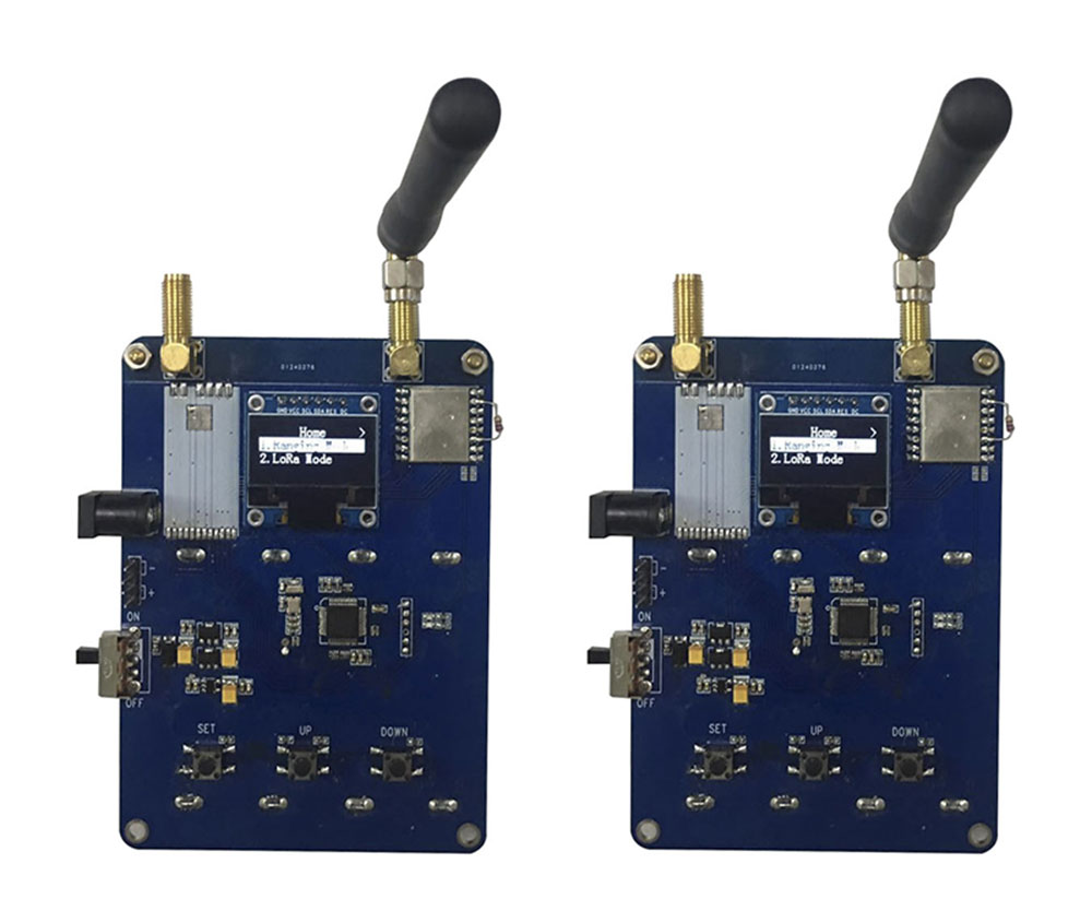
Prepare two SX1280 LoRa module Ranging Demo Boards and select the Ranging mode Ranging Mode interface. (Set the ranging parameters to the same, otherwise the communication will not be normal)
1. Select one set as the ranging host: main interface - ranging mode interface - ranging host interface.
2. The other one is set to the distance measuring slave: main interface - ranging mode interface - ranging from the machine interface.
At this time, the status of the indicator light is observed. The indicator light flashes blue for the LoRa module to communicate normally, and the ranging is successful; In red, the wireless module does not communicate, and the ranging fails. The distance displayed by the ranging display is displayed on the screen of the ranging host, as shown in the figure:
Communication test of SX1280 LoRa module demo board
Prepare the two SX1280 LoRa module Ranging Demo Boards and select the LoRa mode mode interface (set the parameters of LoRa mode to the same, otherwise communication will not be possible)
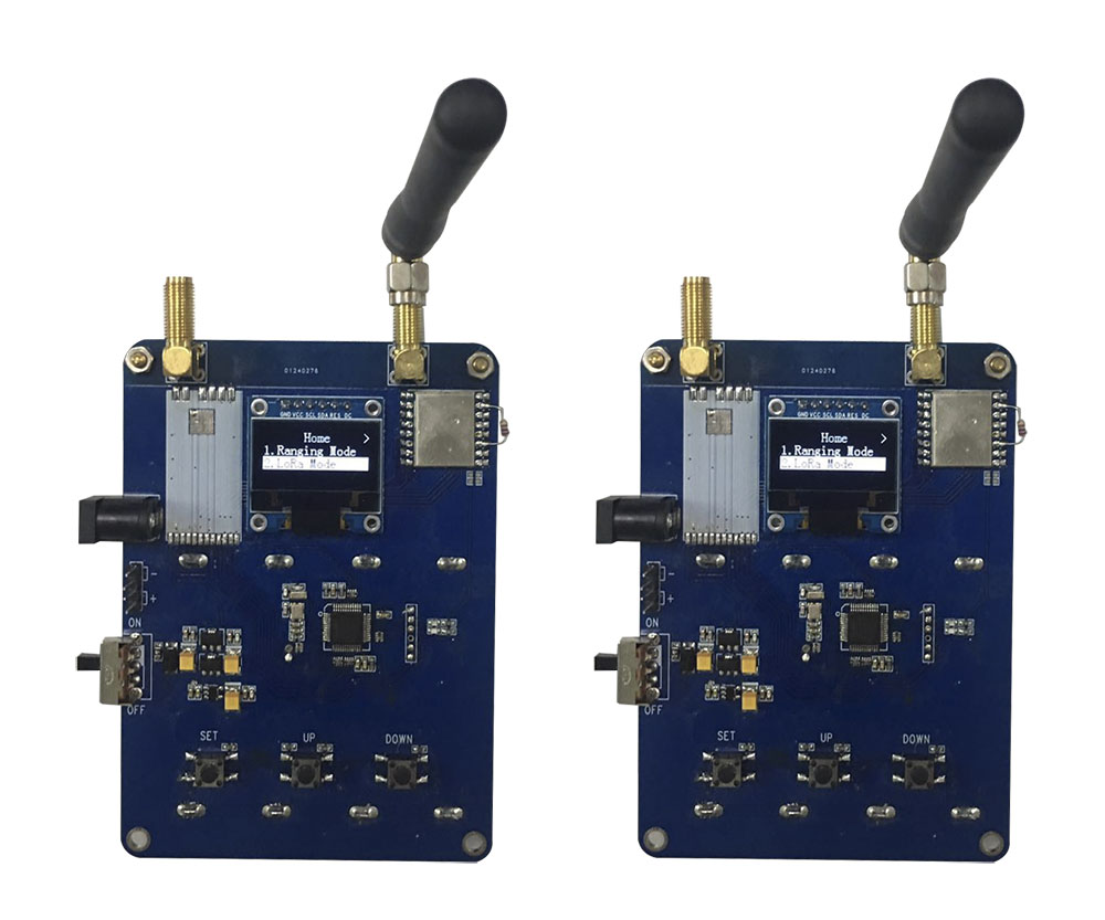
1. Simultaneously choose to enter the LoRa communication interface.
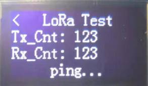
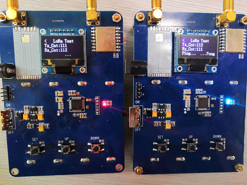
2. The screen of the LoRa communication interface shows that the numbers of Tx_Cnt and Rx_CNT are increasing continuously (the red light indicates that the transmission is successful once, and the blue light indicates that the reception is successful once). Figure:
 +86-755-23080616
 sales@nicerf.com
Website: https://www.nicerf.com/
Address: 309-314, 3/F, Bldg A, Hongdu business building, Zone 43, Baoan Dist, Shenzhen, China


 English


