How to connect uart rf module SV651 to PC configuration parameters
The uart rf module SV651 is widely used, and it is often used in remote meter reading, wireless industrial control, smart home, wireless LED display and other fields. The SV651 module has been deeply loved by users since its listing, but some users do not know how to connect the uart rf module SV651 to the PC for parameter configuration.
How to connect uart rf module SV651 to PC
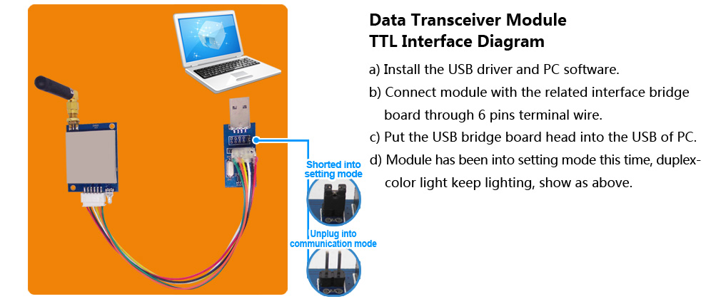
1. Select the right frequency elbow rod antenna and connect the SV651.
2. Use the 6PIN terminal line to connect the corresponding interface of the uart rf module SV651, and connect the other end to the corresponding level adapter board.
3. Insert the USB head of the level adapter board into the USB port of the main computer box to connect to the PC end.
4. After the connection is complete, the blue light of the module is always on, and the module is in the configuration mode at this time.
How to configure parameters for uart rf module SV651
In the configuration mode, the user can configure the relevant parameters of the uart rf module through the PC software. After the PC software is opened, click to open the corresponding COM port (which can be viewed under the device manager), and the PC will read the parameter information of the connected module and display it in the window. The corresponding model and version information are displayed, and the information of "Device Found!" is displayed in the status bar below. When the device is unplugged or there is no response, the lower status bar displays the message "Device Not Found!", and the upper product information box turns gray and invalid. The PC interface after the module is successfully connected is shown in the following figure:
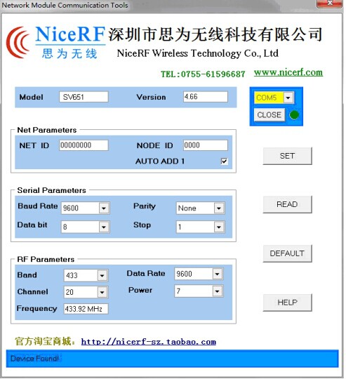
After the uart rf module is connected normally, the module is in the state of "parameter setting". Users can modify the relevant parameters of the module through the PC interface, such as: working frequency band, transceiver channel, air communication rate, transmit power, serial port baud rate, data bit, stop bit, parity bit, NET ID, NODE ID, etc. Then click the [SET] button to set the module. After each parameter is successfully changed, it will return "OK" information. After the PC software receives the OK response, a prompt dialog box for successful operation should pop up; otherwise, "ERROR" will be output, and the operation will pop up. wrong dialog. If there is no response within 0.5s after the PC sends the command, a communication error occurs and a dialog box for an operation error will pop up. These set parameters can be saved when power off. The user clicks the [READ] button, the module will return all parameter information of the current module. The user clicks the [DEFAULT] button to set the parameters of the module to the factory default values. (The serial port and the related parameters of the wireless part in the above PC interface are the factory default values)
The method of connecting the uart rf module SV651 to the PC and configuring the parameters is as described above, I hope it can help you.
 +86-755-23080616
 sales@nicerf.com
Website: https://www.nicerf.com/
Address: 309-314, 3/F, Bldg A, Hongdu business building, Zone 43, Baoan Dist, Shenzhen, China


 English


