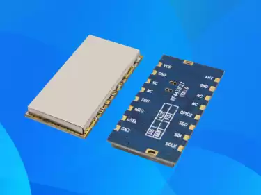
How to detect whether the wireless module communication function is normal
Jun . 2020
The editor first prepares two DEMO function demonstration boards (take LoRaF30 function demonstration board as an example), voltage 3.7V, 1200mAh electric board two.
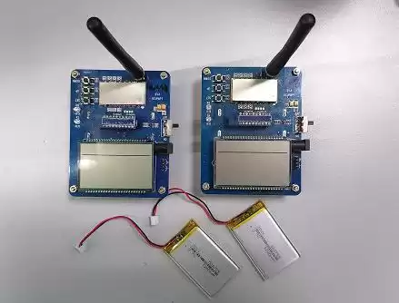
There are three power supply methods for our company's OEMO function demo board. One is to install 4 No. 5 batteries on the back, the other is a DC connector, and the third is a pin interface.
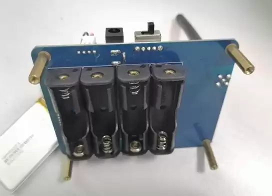
The editor uses the third power supply method, the pin is four pins, and the red, black, and positive of the electric board connection cable are correctly inserted into the second pin and the third pin, and the power is turned on and powered on.
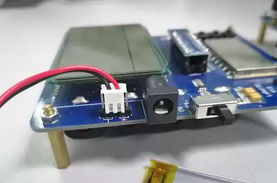
Turn on the power switch and find that the TX numbers are superimposed and the red light flashes at intervals, indicating that the demo version is transmitting data externally.
Next, we set the two demo boards to TX Noraml, RX Normal, FREQ set to 891.5MHz, RPW set to 7, CR set to 45, SF set to 12KHz, BW set to 500HKz, the setting is complete.
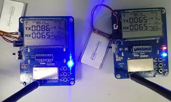
The RX values of the left and right demo board interfaces are all the same as 065, and the TX are 0086 and 0065, because the editor first set the parameters of the left demo board and then set the right demo board, so the TX value of the left demo board is larger than the right side, communication function The test is complete.
 +86-755-23080616
 sales@nicerf.com
Website: https://www.nicerf.com/
Address: 309-315, 3/F, Bldg A, Hongdu business building, Zone 43, Baoan Dist, Shenzhen, China


 English


