HOME > PRODUCTS > FSK FRONT-END MODULES > RF4463PRO-470 : SI4463 100MW 470MHZ RF TRANSMITTER...
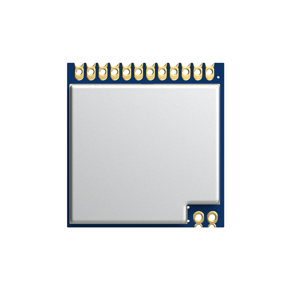
RF4463PRO-470 : Si4463 100mW 470MHz RF Transmitter And Receiver Module
- Our company's RF4463PRO RF transmitter and receiver module uses Silicon Lab si4463, which is a highly integrated wireless ISM band transceiver chip. It has extremely low receiving sensitivity (-126 dBm), coupled with the industry-leading output power of +20 dBm, ensures extended range and improved link performance.
- RF4463PRO uses lead-free technology for production and testing strictly. It also meets RoHS and REACH standards.
Order model | Product type |
RF4463PRO-433 | The working center frequency band is 433MHz |
RF4463PRO-433-CE | The working center frequency band is 433MHz,CE certified version |
RF4463PRO-433-FCC | The working center frequency band is 433MHz,FCC certified version |
RF4463PRO-470 | The working center frequency band is 470MHz |
RF4463PRO-868 | The working center frequency band is 868MHz |
RF4463PRO-868-CE | The working center frequency band is 868MHz,CE certified version |
RF4463PRO-915 | The working center frequency band is 915MHz,has passed FCC and IC |
| Parameter | Min | Typ | Max | Unit | Condition |
| Working Condition | |||||
| Working voltage range | 1.8 | 3.3 | 3.6 | V | |
| Temperature voltage | -40 | 85 | ℃ | ||
| Current Consumption | |||||
| Receiving current | 13.5 | mA | High performance mode | ||
| Receiving current | 10.7 | mA | Low power mode | ||
| Transmitting current | 85 | mA | @20dBm | ||
| Sleep current | < 0.1 | uA | |||
| RF Parameter | |||||
| Frequency range | 403 | 433 | 463 | MHz | @433MHz |
| 470 | 490 | 510 | MHz | @470MHz | |
| 820 | 868 | 880 | MHz | @868MHz, 19dBm | |
| 900 | 915 | 930 | MHz | @915MHz, 18.5dBm | |
| Modulation rate | 0.123 | 1000 | Kbps | FSK | |
| Output power range | -5 | 20 | dBm | ||
| Receiving sensitivity | -126 | dBm | @Data rate=500bps | ||
| Modulation | (G)FSK |
| Chip | si4463 |
| Frequency | 470MHz |
| Output Power | 100mW |
| Interface | SPI |
Features of RF Transmitter And Receiver RF4463PRO
- Frequency Range:470(customizable 142-520MHz)
- Sensitivity up to -126dBm
- Maximum output power:20dBm
- 10mA@Receiving status
- Data transfer rate:0.1-1000Kbps
- (G)FSK, 4(G)FSK, (G)MSK
- OOK and ASK Modulation mode
- 1.8-3.6 V Power supply
- Ultra-low consumption shutdown mode
- Digital received signal strength indicator(RSSI)
- Timed wake-up function
- Antenna automatic matching and two-way switch control
- Configurable date packet structure
- Preamble detection
- 64/128byte transmit and receive data register(FiFo)
- Low-battery detection
- Temperature sensor and 8-bit analog-to-digital converters
- weight:1.3 g
- Operating Temperature Range:-40 ~ +85°C
- Integrated voltage regulator
- Frequency hopping
- Power-on reset function
- Built-in crystal adjustment function
Applications of RF Transmitter And Receiver RF4463PRO
- Remote control
- Remote meter reading
- Home security alarm
- Industrial control
- Home automation remote sensing
- Individual data records
- Toys control
- Sensor network
- Tire pressure monitoring
- Health monitoring
- Wireless PC peripherals
- Tag reading and writing


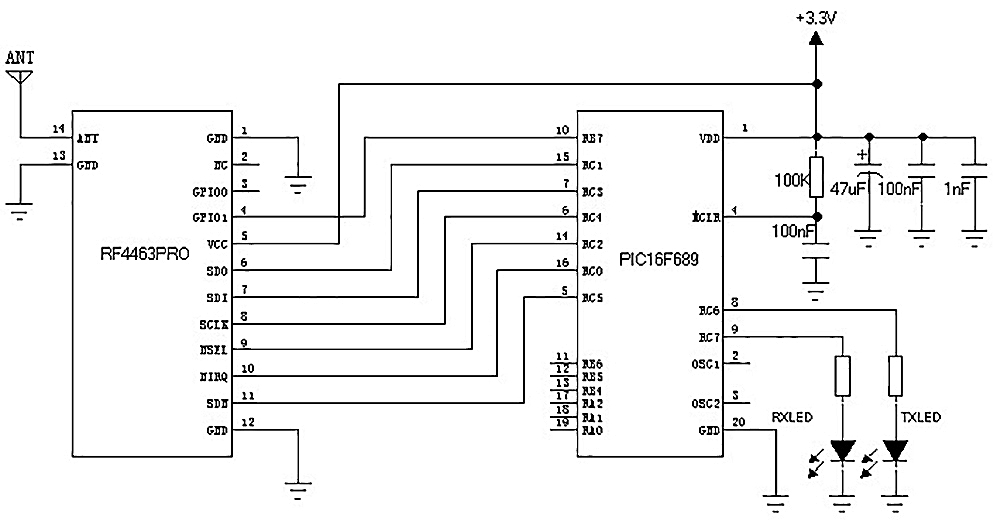
| Pin NO. | Pin Name | Description |
| 1 | GND | Power ground |
| 2 | NC | NC |
| 3 | GPIO0 | Connect directly to the GPIO0 pin of the chip |
| 4 | GPIO1 | Connect directly to the GPIO1 pin of the chip |
| 5 | VCC | Positive power supply 3.3V |
| 6 | SDO | 0~VDD V digital output, provides serial readback function to internal control register |
| 7 | SDI | Serial data input. 0~VDD V digital input. This pin is a 4-wire serial data serial data stream bus. |
| 8 | SCLK | Serial clock input. 0~VDD V digital input. This pin provides a 4-wire serial data clock function. |
| 9 | nSEL | Serial interface select input pin. 0~VDD V digital input. This pin provides select/enable function for 4-wire serial data bus. This signal is also used to indicate burst read/write mode. |
| 10 | nIRQ | Interrupt output |
| 11 | SDN | Chip enable pin. 0~VDD V digital input. SDN=0 in all modes except shutdown mode. When SDN=1, the chip will be completely shut down and the contents of the register will be lost. |
| 12 | GND | Power ground |
| 13 | GND | Power ground |
| 14 | ANT | Connect with 50 ohm coaxial antenna |

Contact us


 English


