


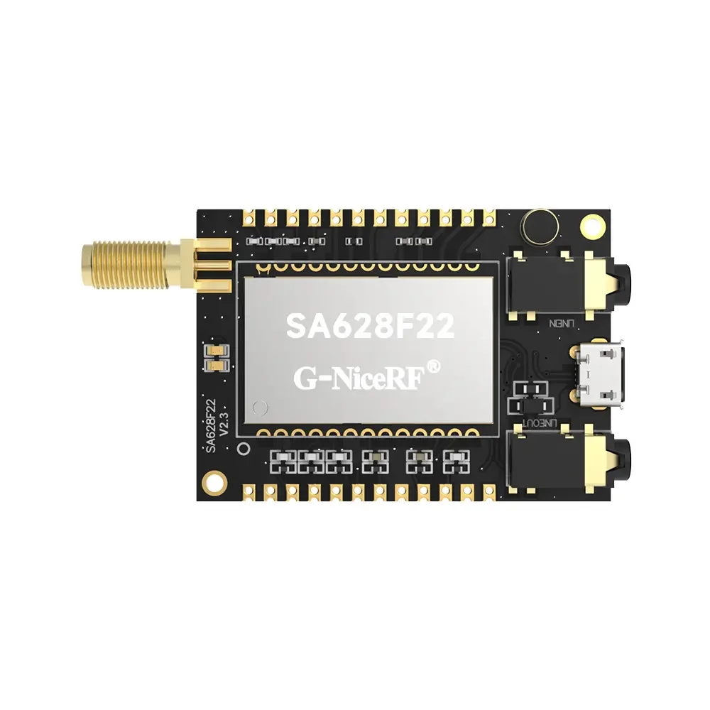
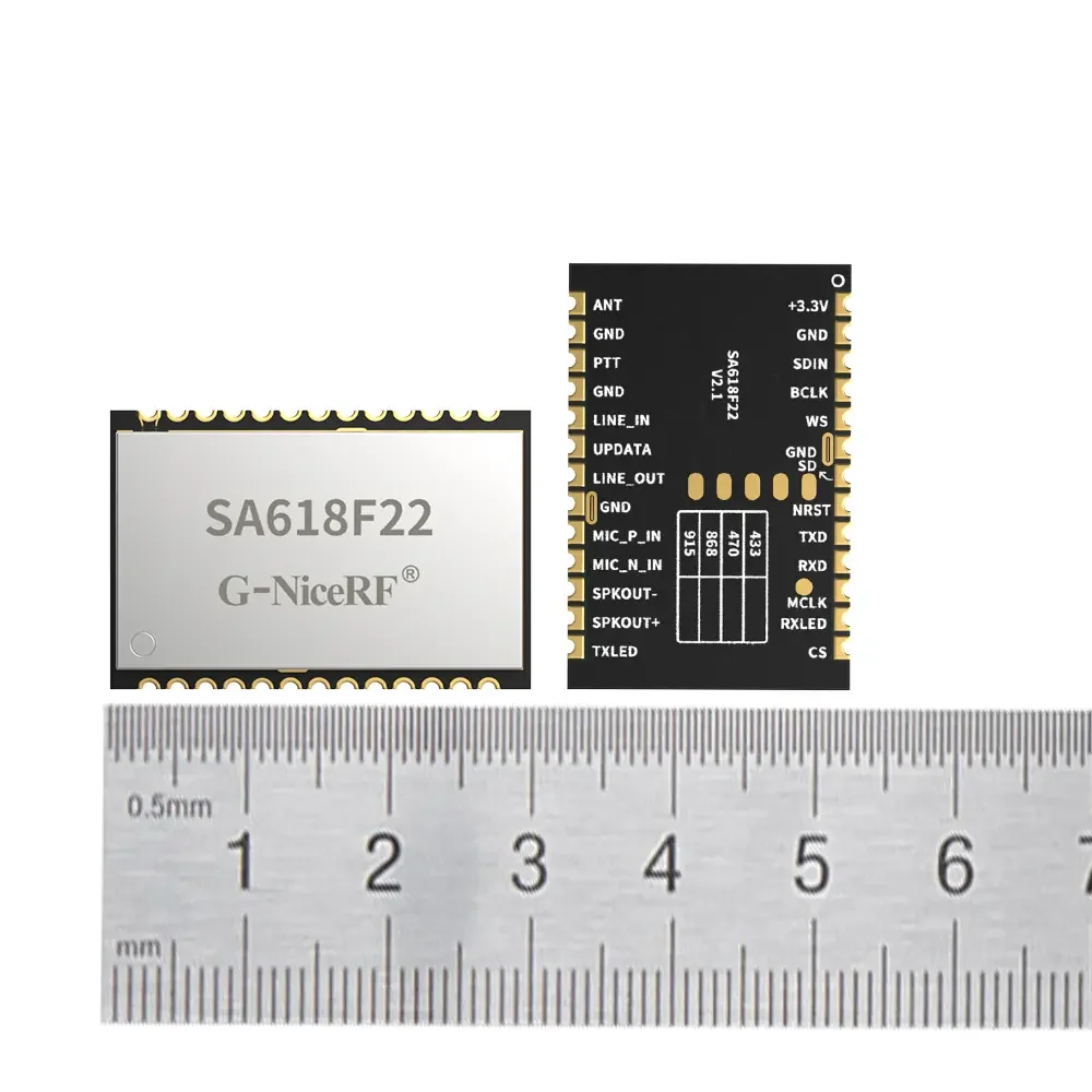
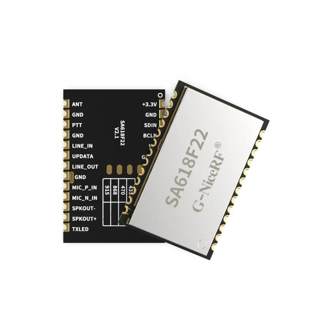
SA628F22 : Easy to Use Full Duplex Wireless Audio Module
Type: Wireless Audio
Certification: Others
Output Power: 160mW,500mW
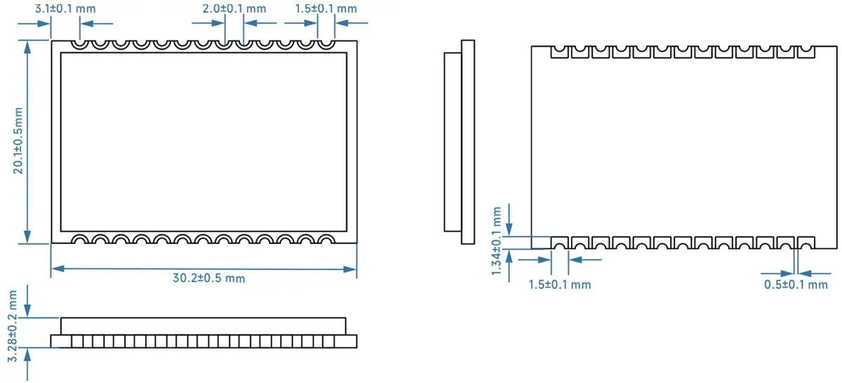
Size:48.1*33.9
| Parameter | Test Conditions | Min. | Typ. | Max. | Unit |
| Operating voltage | 2.3 | 3.3 | 3.6 | V | |
| working temperature | -30 | 25 | 70 | ℃ | |
| Current consumption | |||||
| Sleep current | 12 | uA | |||
| RX current | @ No audio output | 50 | mA | ||
| @8Ω,1W audio output | 300 | ||||
| TX current | 3.3v,@22dBm | 110 | mA | ||
| RF parameter | |||||
| Operating frequency | UHF | 420 | 510 | MHz | |
| Customizable frequency | 150 | 960 | MHz | ||
| Default frequency value for 16 channels | UHF ( 1MHz interval) | 440.125 | 455.125 | MHz | |
| Transmit power | Default:22dBm | 0 | 22 | dBm | |
| Second Harmonic | -40 | dBm | |||
| Bandwidth(BW) | 500 | KHz | |||
| Receiving sensitivity | -117 | dBm | |||
| Audio parameters | |||||
| Modulation sensitivity | 10 | 100 | mV | ||
| Receive signal-to-noise ratio(SNR) | 90 | dB | |||
| frequency response | 60 | 3800 | Hz | ||
| Audio output(line out) | Load 16 Ω | 40 | mW | ||
| Delay parameters | 2 channels | 80 | 100 | 120 | ms |
| 3 channels | 120 | 160 | 180 | ms | |
| 4 channels | 160 | 200 | 240 | ms | |
| 6 channels | 240 | 300 | 360 | ms | |
| 8 channels | 320 | 400 | 480 | ms | |
| Type | wireless audio |
| Output Power | 160mW |
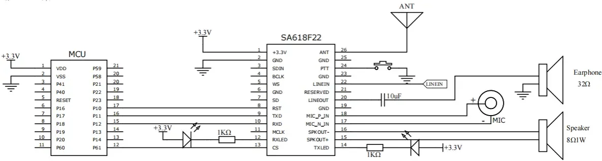
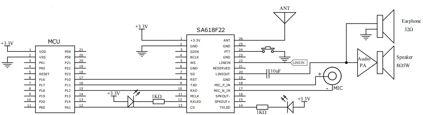
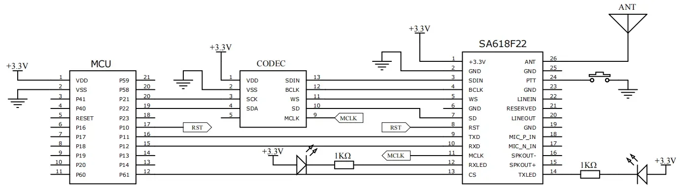
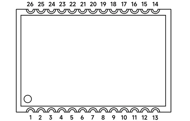
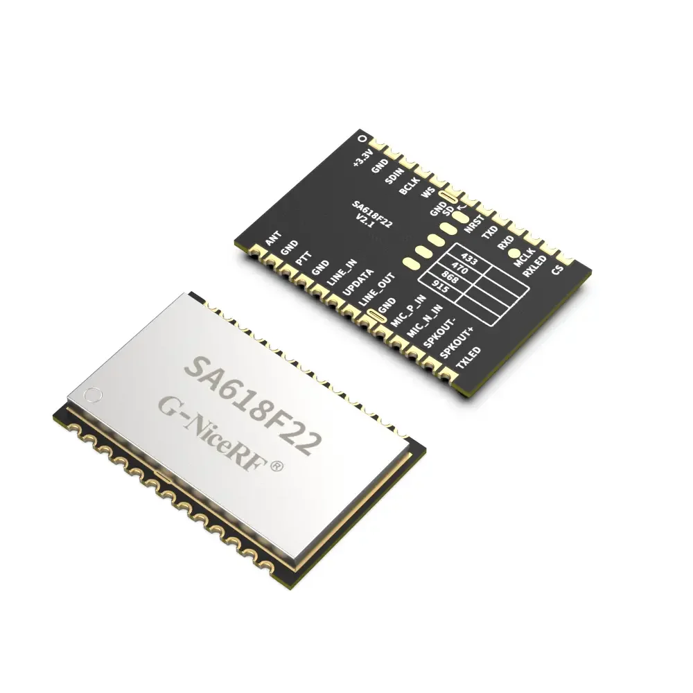
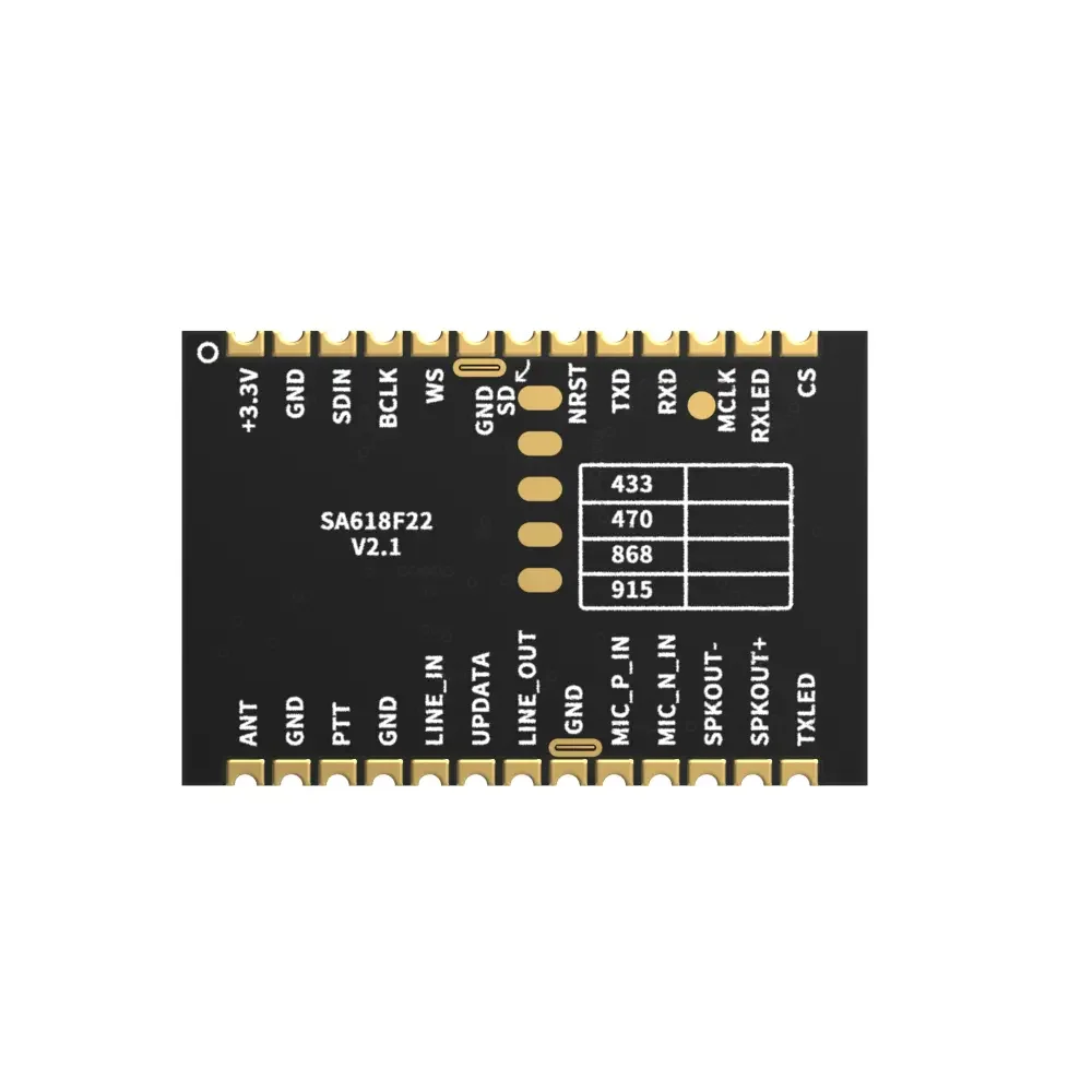
| Pin NO. | Pin name | I/O | Description |
| 1 | +3.3v | 2.3-3.6V | |
| 2,6,19,23,25 | GND | Ground | |
| 3 | SDIN | I | External I2S (0-3.3V) |
| 4 | BCLK | O | External I2S (0-3.3V) |
| 5 | WS | O | External I2S (0-3.3V) |
| 7 | SD | O | External I2S (0-3.3V) |
| 8 | RST | I | Module reset pin, externally pull down for more than 5ms will reset the module |
| 9 | TXD | O | Serial communication |
| 10 | RXD | I | Serial communication |
| 11 | MCLK | O | External I2S (0-3.3V) |
| 12 | RXLED | O | Receiving indicator, connected with external led, turn on by low level output when data or voice received, (suggest 1K ohm resistor for current limitation) |
| 13 | CS | I | Floating input, low level to enter sleep |
| 14 | TXLED | O | Transmitting indicator, connected with external led, turn on by low level output when data or voice is transmitting, (suggest 1K ohm resistor for current limitation) |
| 15 | SPKOUT+ | O | External connect 8Ω 2W speaker |
| 16 | SPKOUT- | O | External connect 8Ω 2W speaker |
| 17 | MIC_N_IN | I | Negative electrode of external microphone |
| 18 | MIC_P_IN | I | Positive electrode of external microphone |
| 20 | LINE_OUT | O | Connected with 16 Ω earphones |
| 21 | Reserved | NC | |
| 22 | LINE_IN | I | Line in ,maximum 1VRMS |
| 24 | PTT | I | Press to talk, pull down to enter transmission mode, pull high or leave open to enter receive mode, pull-up internally, |
| 26 | ANT | Connected with 50ohm Antenna |
Privacy Policy
· Privacy Policy
There is currently no content available
Email:sales@nicerf.com
Tel:+86-755-23080616