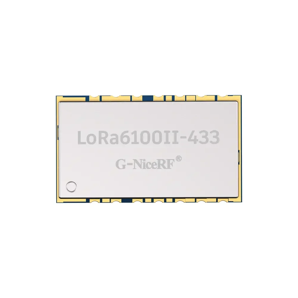
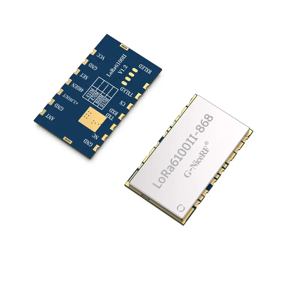
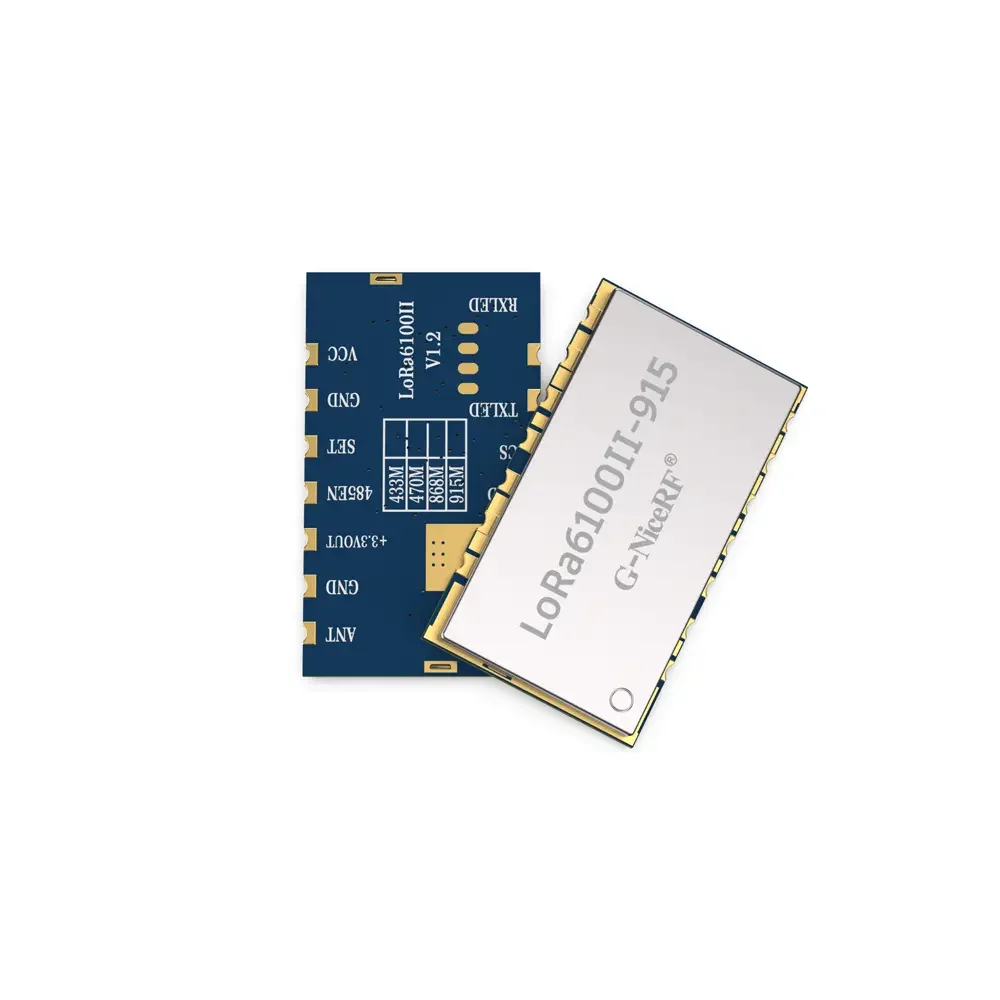


LoRa610Pro : 100mW Embedded Small Size Uart LoRa Module With ESD Protection
Certification: Others
Modulation: LoRa
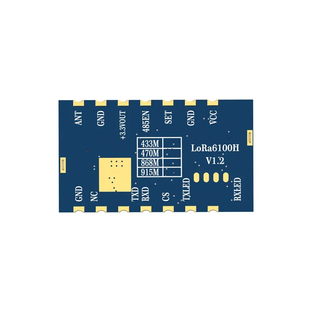
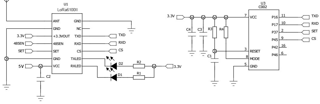
Interface: RS232,RS485,TTL
Output Power: 100mw
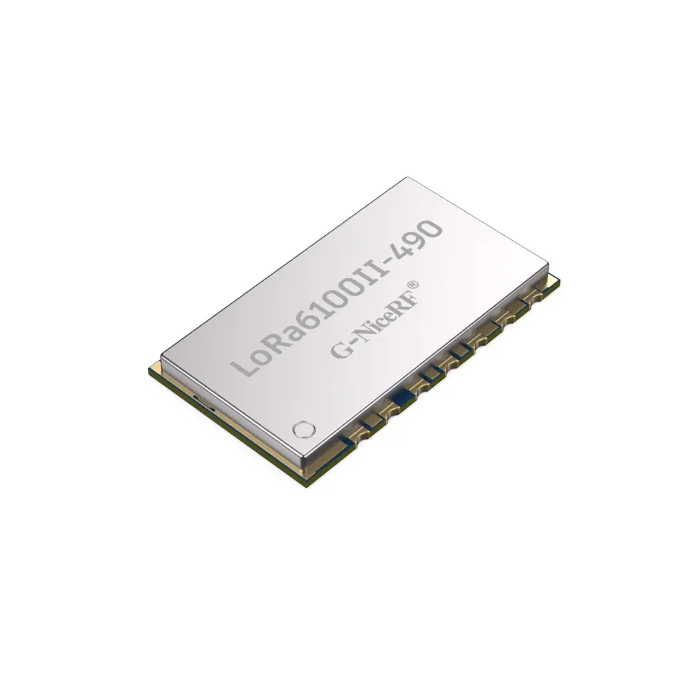
Frequency: 433MHz,470MHz,868MHz,915MHz
Network: MESH,Point-to-point
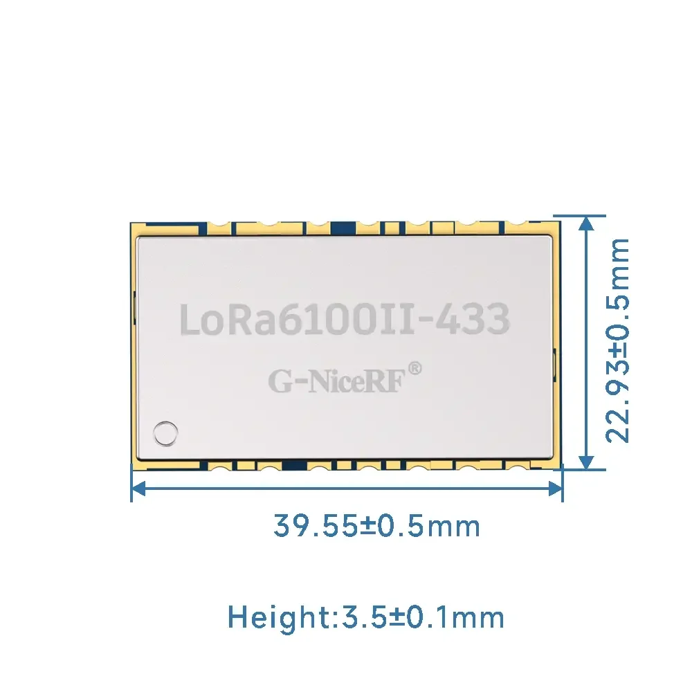
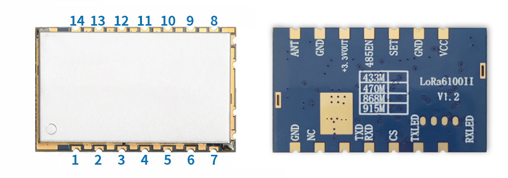
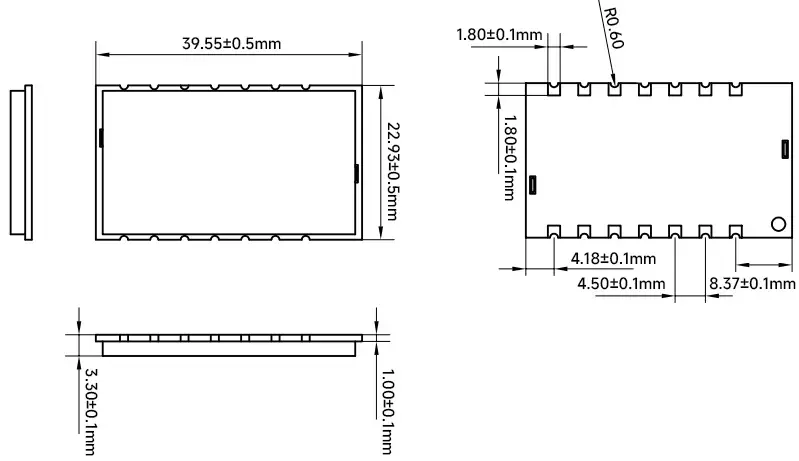
Size:39.55*22.93