Contact Us
HOME > PRODUCTS > SENSOR MONITORING GATEWAY AND NODE > IOT-THS010 : IOT TEMPERATURE AND HUMIDITY SENSOR ...
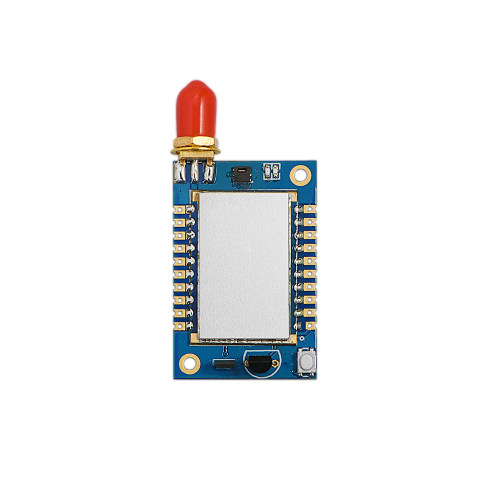
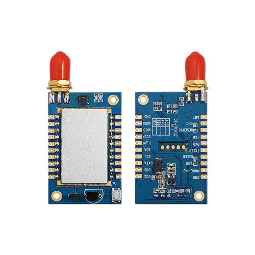
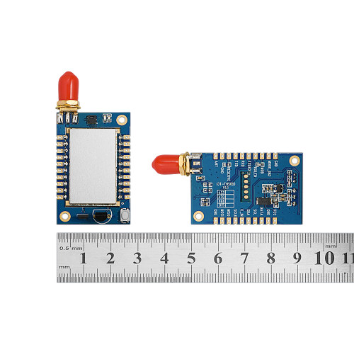
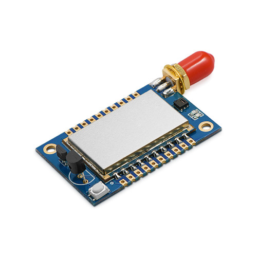
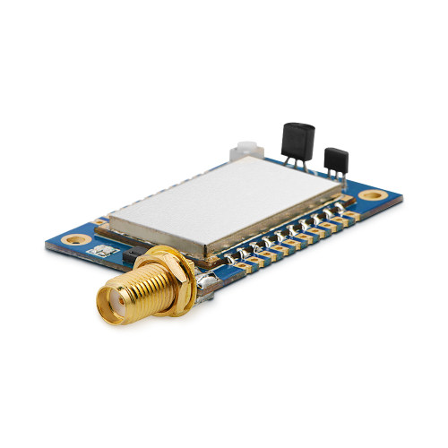
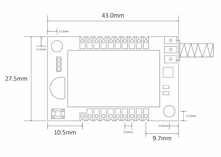
IOT-THS010 : IOT Temperature And Humidity Sensor Monitoring And Switch Status Detection Node
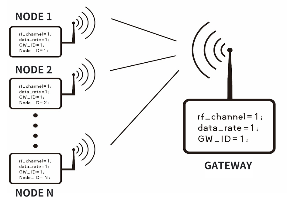
The ultra-low power sensor monitoring star network system is mainly used for sensor data acquisition and control of the Internet of Things. The entire network system is composed of gateway IOT-G010 and node IOT-N010/ IOT-THS010, which adopts the networking mode of wireless star network. A good coordination mechanism and precise scheduling algorithm are used internally between the node and the gateway to avoid collisions between data packets in the air. The communication protocol between the node and the gateway has been implemented by the system, and customers can build a reliable sensor acquisition and control network as long as they follow a simple configuration. The node module IOT-THS010, as the node end of the network, uses a high-performance low-power MCU and a wireless communication module, integrated temperature sensor DS18B20 or temperature and humidity sensor SHT20 and Hall devices. Setting a proper collection interval can achieve a life span of several years. Especially suitable for battery-powered temperature and humidity acquisition and switch state detection systems
| Parameter | Min. | Type. | Max. | Unit | Conditions |
| Operation Conditions | |||||
| Operating voltage range | 3.3 | 5 | 6 | V | |
| Operating temperature range | -40 | 25 | +85 | ℃ | |
| Current Consumption | |||||
| RX Current | <20 | mA | |||
| TX Current | <100 | mA | @20dBm | ||
| Sleep Current | <12 | uA | |||
| RF Parameters | |||||
| Modulation rate | 1.2 | 9.6 | 1000 | Kbps | GFSK |
| Transmit power range | -1 | / | +20 | dBm | Software configurable |
| Receiving sensitivity | -121 | dBm | @1.2Kbps | ||
| Special Function | Sensor acquisition |
Features of Sensor Monitoring Node IOT-THS010
- Node low power consumption
- Star network
- Multi-point data collection (up to 255 for a single gateway)
- Multi-point switch collection (up to 255 for a single gateway)
- Data anti-collision mechanism
- Serial port firmware upgrade
- Programmable Upload time interval
- OTA parameter modification
Applications of Sensor Monitoring Node IOT-THS010
- Temperature and humidity collection
- Switch status detection
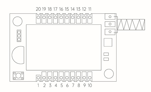
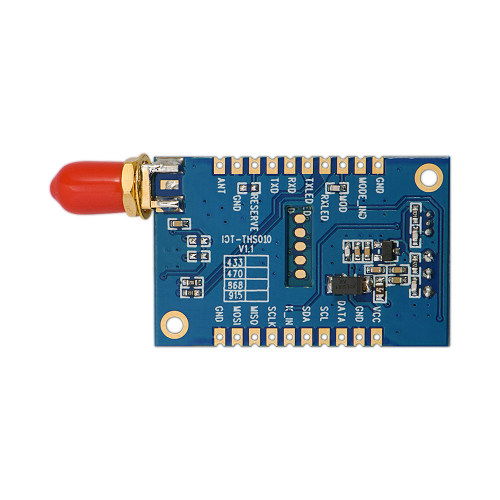
| Pin NO | Pin definition | Description |
| 1 | VCC | Positive power supply (3.3-6V) |
| 2 | GND | Power ground |
| 3 | DATA | The module is connected to the DATA pin of DS18B20, or it can be connected to 18B20 DATA. |
| 4 | SCL | The clock pin of SHT200 is internally connected, such as an external sensor, this pin can be connected. |
| 5 | SDA | The data pin of SHT200 is internally connected, such as an external sensor, this pin can be connected. |
| 6 | K_IN | The output pin of the Hall device is internally connected, and the magnetic sensor can be externally connected. |
| 7 | SCLK | Keep |
| 8 | MISO | Keep |
| 9 | MOSI | Keep |
| 10 | GND | Power ground |
| 11 | ANT | Connect the antenna (50 ohm copper shaft antenna) |
| 12 | GND | Antenna ground |
| 13 | Reserve | Keep |
| 14 | TXD | Serial communication data transmission |
| 15 | RXD | Serial communication data reception |
| 16 | TXLED | The red light on the internal connection board, the transmitting indicator light, the low level lights up. |
| 17 | RXLED | The blue light on the internal connection board, the receiving indicator light, the low level is on. |
| 18 | SET_MODE | Set the pin, which is connected with the buttons on the board, pull it down for 3s to enter the setting mode, pull it down for 15s to restore the factory settings |
| 19 | SET_MODE_IND | Setting mode indication, output low when entering setting mode; input high when exiting |
| 20 | GND | Power ground |