

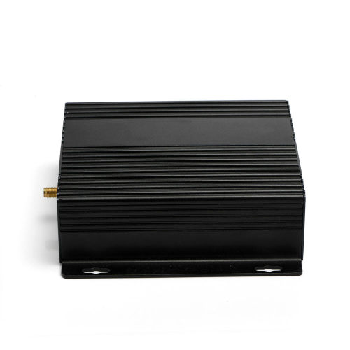
LG1301-PF : LoRaWAN Gateway Transmitter And Receiver RF Module
Modulation: LoRa
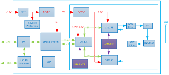
Chip: SX1301
Interface: Ethernet
Output Power: 250mW
Frequency: 433MHz,470MHz,868MHz,915MHz
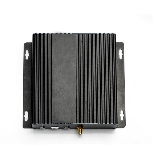
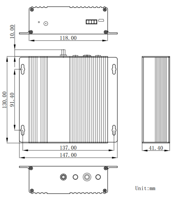
Size:147*130
| Parameter | Min | Typ. | Max | Unite | Condition | |
| Working Condition | ||||||
| Working voltage range | 5 | 12 | 30 | V | ||
| Temperature voltage | -40 | 85 | ℃ | |||
| Current Consumption | ||||||
| Receiving current | <280 | mA | @12v,9 channels all open | |||
| Transmitting current | <450 | mA | @12v,TX=24dBm | |||
| Parameter | ||||||
| Frequency range | 429 | 433 | 440 | MHz | @433MHz | |
| 470 | 480 | 490 | MHz | @470MHz | ||
| 860.75 | 868.3 | 874.5 | MHz | @868MHz | ||
| 902 | 915 | 928 | MHz | @915MHz | ||
| Output power | 0 | 24 | dBm | |||
| Receiving sensitivity | -133 | dBm | @SF=10,,BW=125kHz | |||
★ Note: the following parameters is VCC = 3.3, with 50 ohm copper axis test instrumentation.
| Interface | Uart |
| Chip | SX1301 |
| Frequency | 433MHz,470MHz,868MHz,915MHz |
| Output Power | 250mW |
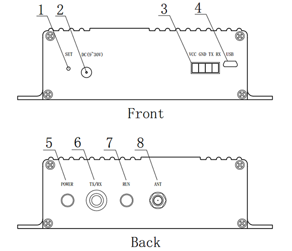
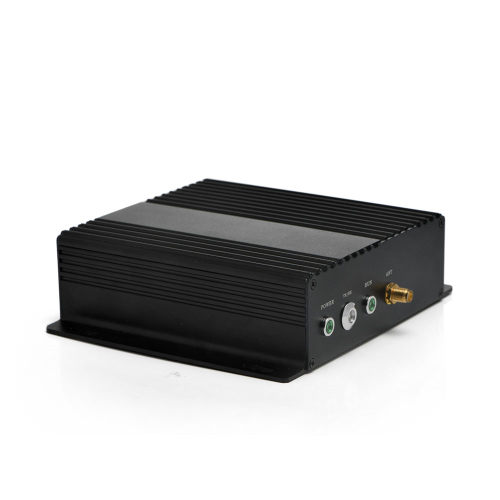
| No. | Definition | Description |
| 1 | SET | Press to enter/exit setting mode |
| 2 | Power In | Voltage input DC 5~30V |
| 3 | Data interface | TTL or RS232 ,RS485 Interface Three choices |
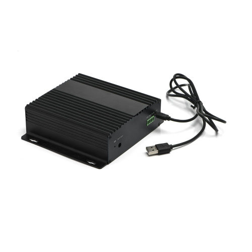
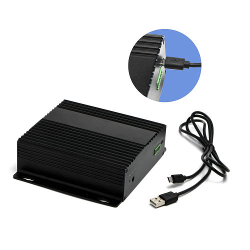
| 4 | Micro USB | System parameter configuration |
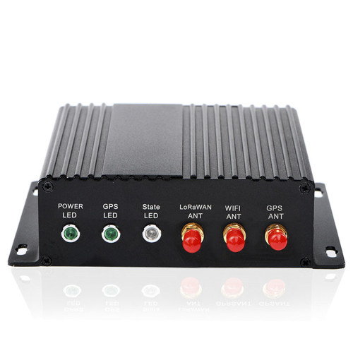
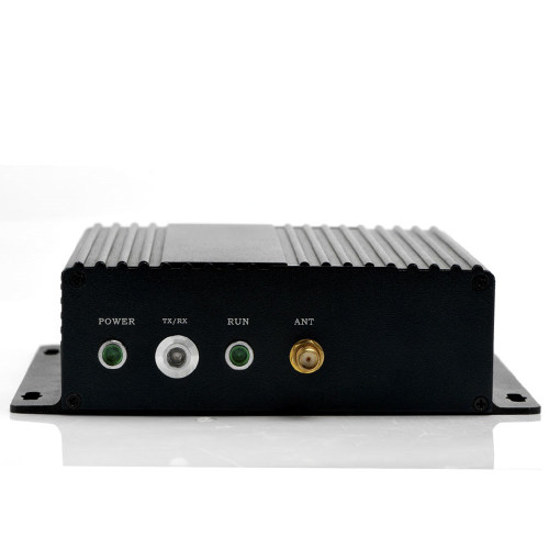
| 5 | Power LED | Green LED , indication of powered on |
| 6 | LED for Tx/Rx | Red LED blinks once when Tx one packet and Blue led blinks once when one packet is received and verified OK. |
| 7 | LED for Status | Light on in setting mode, and blinks once per second in normal mode |
| 8 | Antenna | Connected with 50 Antenna |
| Definition of Data interface | |||
| No. | Definition | Type | Description |
| 1 | +3.3V | Power (VCC) | DC 5~30V Input |
| 2 | GND | Power (GND) | Ground |
| 3 | TXD | Output | Connected with the RXD of external device |
| 4 | RXD | Input | Connected with the TXD of external device |
Privacy Policy
· Privacy Policy
There is currently no content available
Email:sales@nicerf.com
Tel:+86-755-23080616