Contact Us
HOME > PRODUCTS > TRANSPARENT WIRELESS UART MODULES > LORA MODULATION > LORA600PRO : 100MW LORA RF MODULE WITH ANTENNA AND...
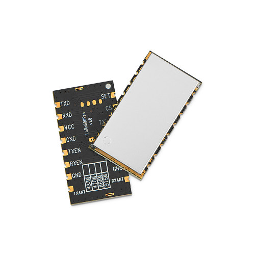
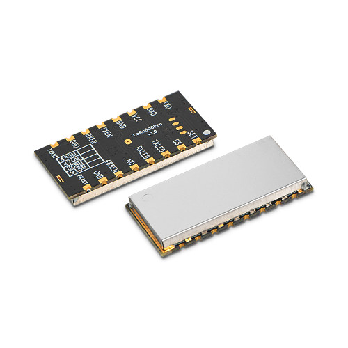
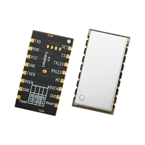
LoRa600Pro : 100mW LoRa RF Module With Antenna And ESD Protection
- LoRa600Pro adds a dual-antenna design on the basis of LoRa610pro, which separates the transmitting antenna from the receiving antenna to better meet the needs of specific applications. The module is designed with an output power of 100mw, and the embedded small-size design can be widely used in industries such as wireless remote transmission control.
- LoRa600Pro strictly uses lead-free process for production and testing, and meets RoHS and Reach standards.
- Note: The LoRa Pro series can be configured to be compatible with our previous LoRa uart RF module.
- Hardware Features:
- 1. Dual antenna output.
- 2. Overcurrent protection circuit.
- 3. Built-in hardware anti-crash self-reset circuit to resist strong external interference signals.
- Software features:
- 1. AES128 data encryption.
- 2. LBT (Listen Before Talk).
- 3. Node/route/node+route optional in MESH mode.
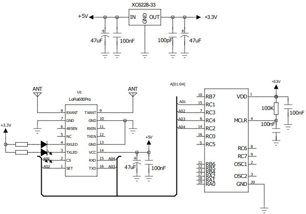
Note: The module is internally regulated by 3.3V LDO. The CS pin and SET pin control are 3.3V levels. TXD and RXD are also 3.3V levels.
| Parameters | Min. | Typ. | Max. | Unit | Condition |
| Working Condition | |||||
| Voltage range | 3.3 | 5.0 | 6.5 | V | |
| Operating Temperature | -40 | 25 | +85 | ℃ | |
| Current Consumption | |||||
| Rx current | < 15 | mA | TTL level | ||
| Tx current | < 130 | mA | |||
| Sleep current | < 200 | uA | |||
| RF Parameters | |||||
| Frequency range | 414.92 | 433.92 | 453.92 | MHz | @433MHz |
| 470.92 | 490.92 | 509.92 | MHz | @490MHz | |
| 849.92 | 868.92 | 888.92 | MHz | @868MHz | |
| 895.92 | 914.92 | 934.92 | MHz | @915MHz | |
| Data rate | 91 | 656 | 17353 | bps | @LoRa |
| Output power | 4 | 18 | +20 | dBm | Software level 7 adjustable |
| Sensitivity | -139 | dBm | @91bps | ||
| Interface | TTL |
| Network | MESH |
| Frequency | 433MHz,470MHz,868MHz,915MHz |
| Modulation | LoRa |
| Output Power | 100mW |
Features of Uart RF Module LoRa600Pro
- Dual antenna design
- AES128 data encryption method
- No blind zone without distance limitation
- Single module open transmission distance of 5Km @ low rate
- Frequency band: 433/470/868/915 MHz for option
- Up to 40 communication channels in the same frequency band
- Diversified serial port parameters
- Operating voltage range: 3.3~ 6.5 V
- LBT (Listen Before Talk) function optional
- Node/route/node+route optional in MESH mode
- Hop level in MESH mode
- CRC encryption optional
- Built-in hardware reset protection circuit
- LoRa modulation
- TTL interface
- Sensitivity up to -139 dBm
- Maximum output power: 100 mW (+20 dBm)
- Operating temperature range: -40 ~ +85 °C
Applications of Uart RF Module LoRa600Pro
- Remote control
- Remote meter reading
- Industrial data collection
- Home automation telemetry
- Wireless data communication
- Access control system
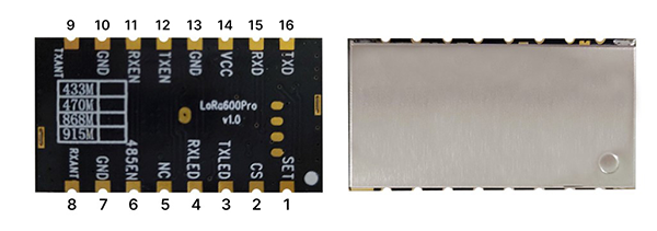
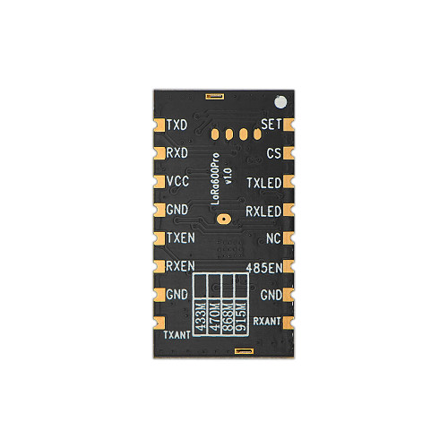
| NO. | PIN | I/O | Level standard | Description |
| 1 | SET | I | 0-3.3 | Configuration parameter enable (low level enable parameter configuration, default high level output) |
| 2 | CS | I | 0-3.3 | Module enable pin(Built-in pull-up) Note: Default factory version: Sleep current <200uA, normal communication when CS is pulled high or suspended, and sleep when low level; Low-power version: Sleep current <15uA, normal communication when CS is pulled low, and sleep when pulled high or suspended |
| 3 | TXLED | I | 0-3.3 | Transmit signal indicator light, low level lights up, default high level |
| 4 | RXLED | I | 0-3.3 | Receive signal indicator, low level lights up, default high level |
| 5 | NC | |||
| 6 | 485EN | O | 0-3.3 | Can be connected to externally expanded 485 level control conversion pin |
| 7,10,13 | GND | 0 | Connect the negative pole of the power supply and the ground wire | |
| 8 | RX ANT | I | RF signal input, connect with 50 ohm antenna | |
| 9 | TX ANT | O | RF signal output, connect with 50 ohm antenna | |
| 11 | RXEN | O | 0-3.3 | Receive enable control pin, high when receiving, low when transmitting. |
| 12 | TXEN | O | 0-3.3 | Transmit enable control pin, low when receiving, high when transmitting. |
| 14 | VCC | I | Connect to the positive pole of the power supply (typical value 5V) | |
| 15 | RXD | I | 0-3.3 | Module serial communication input |
| 16 | TXD | O | 0-3.3 | Module serial communication output |