Contact Us
HOME > PRODUCTS > TRANSPARENT WIRELESS UART MODULES > (G) FSK MODULATION > MESH NETWORK UART RF MODULES SV-MESH SERIES
Mesh Network Uart RF Modules SV-MESH Series
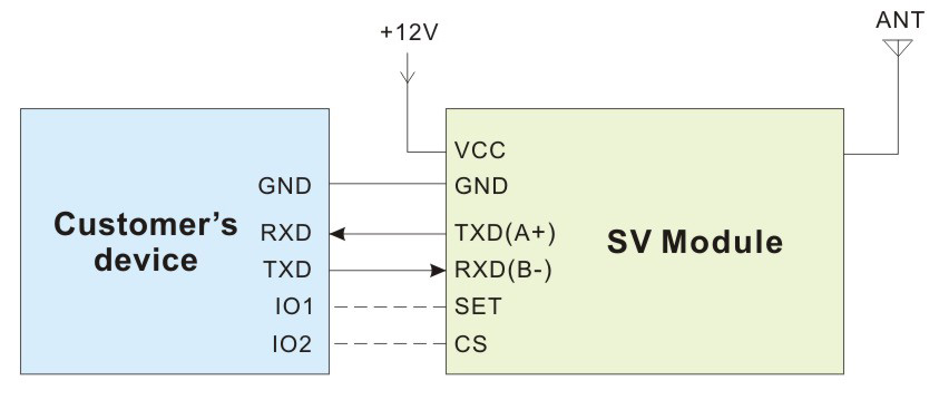
- SV-MESH series are ultra long distance MESH network uart rf modules, which adopts the high performance Silicon Labs Chips. They have NODE and ROUTER working modes, can be as repeaters automatically. It is easy to build network without blind area or distance limitation. To avoid the interference, SV-MESH provides 40 frequency channels and configurable Net ID. SV-MESH is flexible but easy to use , it comes with many parameters, such as: frequency, data rate, output power, Net ID, Node ID. Users can configure the parameters through PC or customer’s own device.
- SV-MESH strictly uses lead-free process for production and testing, and meets RoHS and Reach standards.
| Parameters | Min. | Typ. | Max. | Unit | Condition |
| Working Condition | |||||
| Voltage range | 3.3 | 5.0 | 6.5 | V | @100mW |
| 3.3 | 5.0 | 6.5 | V | @500mW | |
| 4.5 | 5.0 | 6.5 | V | @2W | |
| 9 | 12 | 18 | V | @3W | |
| 9 | 12 | 30 | V | @5W | |
| 4.5 | 5.0 | 5.5 | V | @USB port | |
| Current Consumption | |||||
| Sleep current | < 5 | uA | @100mW、500mW、2W | ||
| < 5 | mA | @3W、5W | |||
| Rx current | 25 | mA | @TTL Level | ||
| 34 | mA | @RS485 Level | |||
| 33 | mA | @RS232 Level | |||
| 26 | mA | @USB Level | |||
| Tx current | < 95 | mA | @100 mW | ||
| < 350 | mA | @500 mW | |||
| < 900 | mA | @2W | |||
| < 600 | mA | @3W | |||
| < 1.8 | A | @5W | |||
| RF Parameters | |||||
| Frequency range | 414.92 | 433.92 | 453.92 | MHz | @433 MHz |
| 470.92 | 470.92 | 509.92 | MHz | @470 MHz | |
| 849.92 | 868.92 | 888.92 | MHz | @868 MHz | |
| 895.92 | 914.92 | 934.92 | MHz | @915 MHz | |
| Output power | -1 | +20 | +20 | dBm | 100 mW |
| +20 | +27 | +27 | dBm | 500 mW | |
| +13 | +33 | +33 | dBm | 2 W | |
| +15 | +35 | +35 | dBm | 3 W | |
| +30 | +37 | +37 | dBm | 5 W | |
| Data rate | 1.2 | 9.6 | 115.2 | Kbps | GFSK |
| Rx Sensitivity | -121 | dBm | @1.2Kbps | ||
| Interface | TTL,RS232,RS485,USB |
| Network | MESH |
| Frequency | 433MHz,470MHz,868MHz,915MHz |
| Modulation | (G)FSK |
| Output Power | 100mW,500mW,1W,2W,3W,5W |
Features of Uart RF Module SV-MESH Series
- Repeat automatically
- GFSK modulation
- 40 channels
- 4 bytes Net ID
- Default 2 bytes Node ID
- Serial parameters configurable
- RSSI
- TTL/RS232/RS485/USB for option
- Max output power: 100mW~5W for option
- Frequency band: 433/470/868/915MHz for option
- Sensitivity up to -121 dBm
- Working temperature: -40 ~ +85 °C
Applications of Uart RF Module SV-MESH Series
- Robot control
- Remote control telemetry
- Industrial data acquisition
- Wireless data communication
- Access control system
- Remote meter reading
- Security system
- Home automation
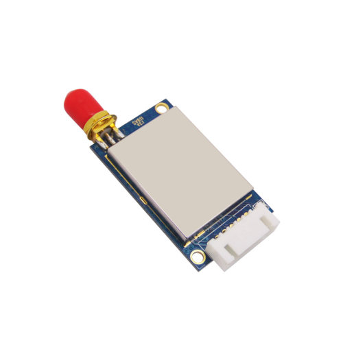
SV610:
| Pin No. | Definition | Description |
| 1 | VCC | Connected to the positive power supply (typical 5V) |
| 2 | GND | Connected to ground |
| 3 | TXD | TXD of the module and connect to external RXD |
| 4 | RXD | RXD of the module and connect to external TXD |
| 5 | SET | Configuration mode enable (low to enter into the setting mode, leave open or connect high level to exit setting mode) Valid when CS Pin is high or leave open. |
| 6 | CS | Module working Enable(Pull Low to make the module enter into sleep mode, Leave open or connect high level make the module enter into normal working mode) |
| 7 | GND | Connected to ground |
| 8 | ANT | Connected with antenna(50ohm copper coaxial antenna) |
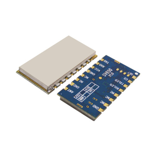
SV650:
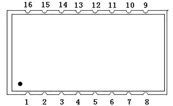
| Pin No. | Definition | Description |
| 1 | SET | Configuration mode enable (low to enter into the setting mode, leave open or connect high level to exit setting mode) Valid when CS Pin is high or leave open. |
| 2 | CS | Module working Enable(Pull Low to make the module enter into sleep mode, Leave open or connect high level make the module enter into normal working mode) |
| 3 | TXLED | LED Indicator for transmission(active when low level) |
| 4 | RXLED | LED Indicator for reception(active when low level) |
| 5、6、7、11、12 | NC | Null |
| 8、10、13 | GND | Connected to ground |
| 9 | ANT | Connected with antenna(50ohm copper coaxial antenna) |
| 14 | VCC | Connected to the positive power supply (typical 5V) |
| 15 | RXD/B | RXD of the module and connect to external TXD (@485 level, connect with B to output ) |
| 16 | TXD/A | TXD of the module and connect to external RXD (@485 level, connect with A to output) |
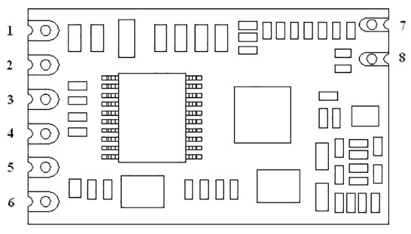
SV611、SV651 series:
| Pin No. | Definition | Description |
| 1 | VCC | Connected to the positive power supply (typical 5V) |
| 2 | GND | Connected to ground |
| 3 | TXD/A | TXD of the module and connect to external RXD (@485 level, connect with A to output) |
| 4 | RXD/B | RXD of the module and connect to external TXD (@485 level, connect with B to output ) |
| 5 | SET | Configuration mode enable (low to enter into the setting mode, leave open or connect high level to exit setting mode) Valid when CS Pin is high or leave open. |
| 6 | CS | Module working Enable(Pull Low to make the module enter into sleep mode, Leave open or connect high level make the module enter into normal working mode) |
SV612、SV652、SV6202 series:
| Pin No. | Definition | Description |
| 1 | VCC | Connected to the positive power supply (typical 5V) |
| 2 | GND | Connected to ground |
| 3 | TXD/A | TXD of the module and connect to external RXD (@485 level, connect with A to output) |
| 4 | RXD/B | RXD of the module and connect to external TXD (@485 level, connect with B to output ) |
| 5 | SET | Configuration mode enable (low to enter into the setting mode, leave open or connect high level to exit setting mode) Valid when CS Pin is high or leave open. |
| 6 | CS | Module working Enable(Pull Low to make the module enter into sleep mode, Leave open or connect high level make the module enter into normal working mode) |
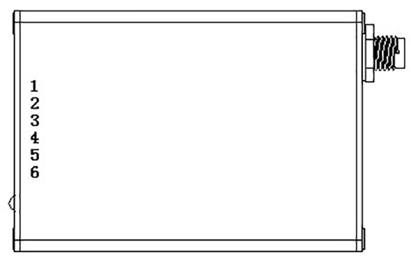
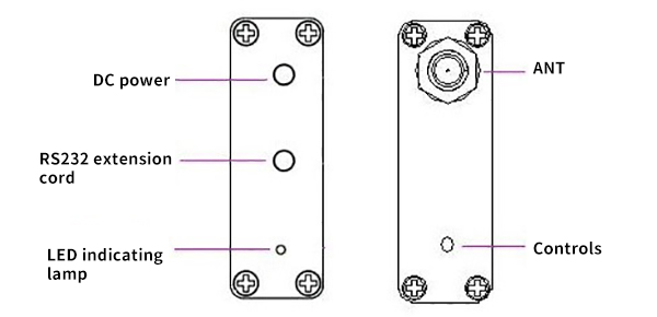
SV613、SV653 series:
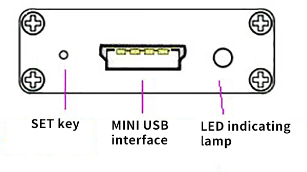
SV614、SV654 series:
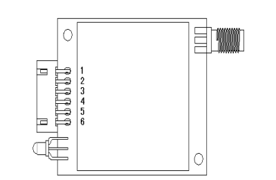
SV6300 series:
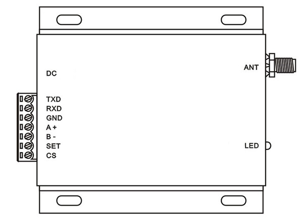
| Pin No. | Definition | Description |
| 1 | TXD | TXD of the module and connect to external RXD |
| 2 | RXD | RXD of the module and connect to external TXD |
| 3 | GND | Connected to ground |
| 4 | A + | Serial communication TXD (RS485 Level) |
| 5 | B - | Serial communication RXD ( RS485 Level) |
| 6 | SET | Configuration mode enable (low to enter into the setting mode, leave open or connect high level to exit setting mode) Valid when CS Pin is high or leave open. |
| 7 | CS | Module working Enable(Pull Low to make the module enter into sleep mode, Leave open or connect high level make the module enter into normal working mode) |
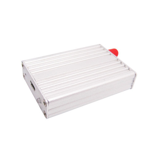
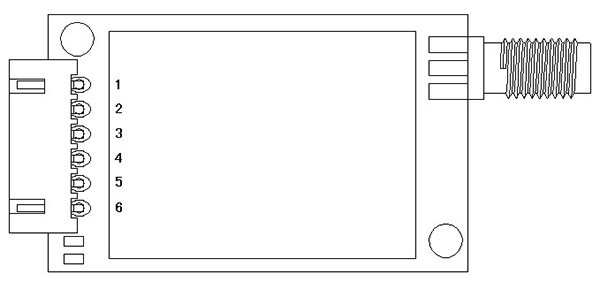
SV6500 series:
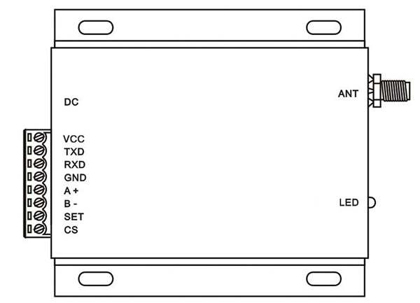
| Pin No. | Definition | Description |
| 1 | VCC | Connect to the positive power supply |
| 2 | TXD | Connect to TXD for TTL or RS232 interface |
| 3 | RXD | Connect to RXD for TTL or RS232 interface |
| 4 | GND | Connected to ground |
| 5 | A+ | Connect to A+ for RS485 interface |
| 6 | B- | Connect to B- for RS485 interface |
| 7 | SET | Configuration mode enable (low to enter into the setting mode, leave open or connect high level to exit setting mode) Valid when CS Pin is high or leave open. |
| 8 | CS | Module working Enable(Pull Low to make the module enter into sleep mode, Leave open or connect high level make the module enter into normal working mode) |
SV610 Dimensions:
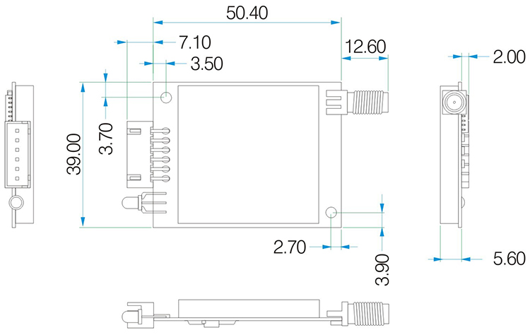
SV611 Dimensions:
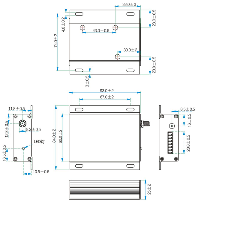
SV650 Dimensions:
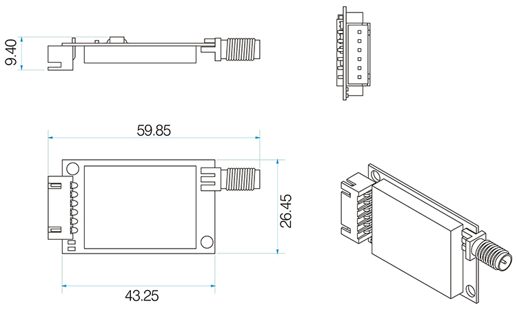
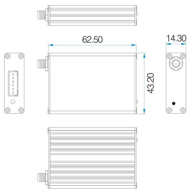
SV651 Dimensions:
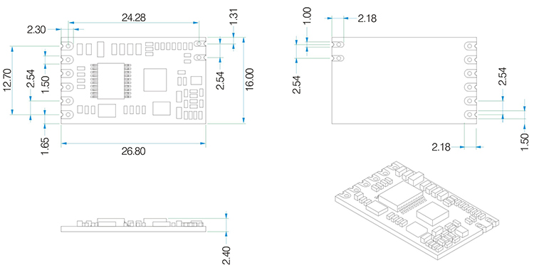
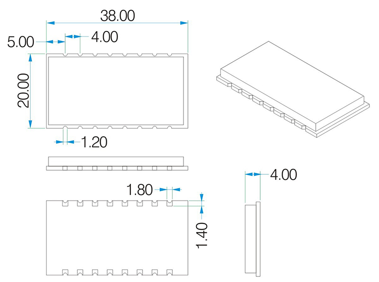
SV612、SV652、SV6202 Dimensions:
SV6300、SV6500 Dimensions: